EasyManuals Logo

Epson LS3-401 series User Manual

Epson LS3-401 series
186 pages
To Next Page IconTo Next Page
To Previous Page IconTo Previous Page
Page #19 background imageLoading...
Page #19 background image
Setup & Operation 1. Safety
LS Rev.10 5
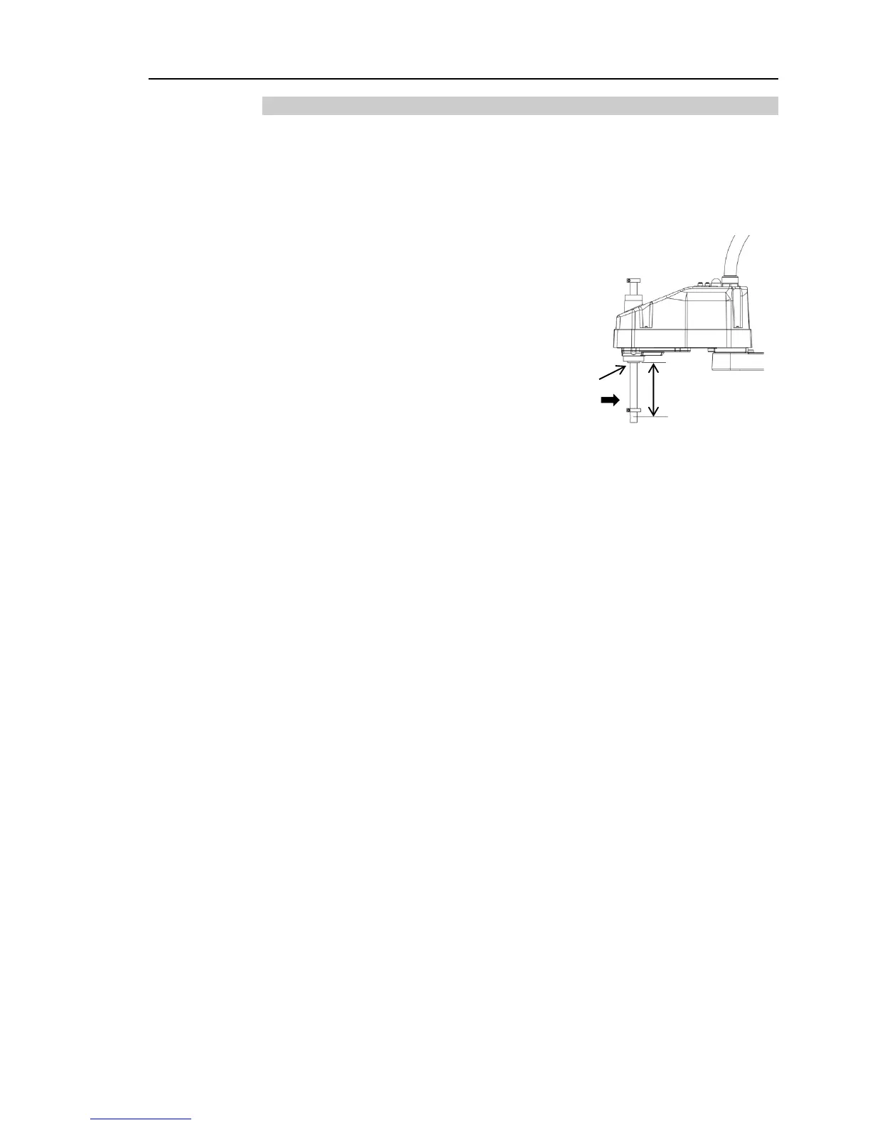
1.2.1 Strength of the Ball Screw Spline
If a load exceeding the allowable value is applied to the ball screw spline, it may not work
properly due to deformation or breakage of the shaft. If the ball screw spline is applied
the load exceeding the allowable value, it is necessary to replace the ball screw spline unit.
The allowable loads differ depending on distance where the load is applied to. For
calculating the allowable load, see the calculation formula below.
[Allowable bending moment]
LS3: M=13,000 N
mm
LS6: M=27,000 N
mm
Example: If 100 N
load is applied
at 200 mm from
the end of the spline nut
[Moment]
M=F
L
100
200
20,000 N
mm
End of the
spline nut
F
L

Table of Contents

Questions and Answers:

Question and Answer IconNeed help?

Do you have a question about the Epson LS3-401 series and is the answer not in the manual?

Epson LS3-401 series Specifications

General IconGeneral
BrandEpson
ModelLS3-401 series
CategoryRobotics
LanguageEnglish

Related product manuals