Maintenance 8. Arm #4
LS Rev.10 127
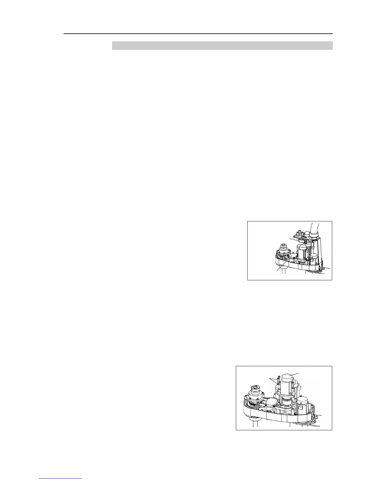
8.2.1 U2 Belt
Push down the shaft to its lower limit while pressing the brake release switch. Be
sure to keep enough space and prevent
the end effector hitting any
The brake release switch affects only Joint #3. When the brake release switch
is pressed, the Joint #3 brake is released.
Be careful of the shaft while the brake release switch is being pressed
the shaft may be lowered by the weight of an end effector.
The brake release switch is applied to both Joints #3 and Joint #4.
When the brake release switch is pressed, the respective brakes of the Joint #3
and Joint #4 are released simultaneously.
Be careful of the shaft falling and rotating while the brake release switch
the shaft may be lowered by the weight of an end
Maintenance: 3.1 Arm Top Cover.
Replacing the Control Board.
Remove one screw that mounts the
Cut off the wire tie binding the cables.
binding the Joint #3 brake cable to the Arm #2 column.
At this point, do not cut off a wire tie (in the duct fittings outlet) that binds the cables
to the User Plate.
Disconnect the following connectors.
Connectors X31, X32, X35, X41, X231, X241 (Hold the claw to remove.)
Maintenance: 3.5 User Plate.
the screws securing the Joint #3

 Loading...


