Maintenance 9. Bellows
LS Rev.10 139
bellows, move the shaft to its lower limit.
To attach the lower bellows, move the shaft to its upper limit.
To move the shaft up/down, press and hold the brake release switch.
Be sure to keep enough space and prevent the
hitting any peripheral
equipment.
The brake release switch affects only Joint #3. When the brake release switch
is pressed, the Joint #3 brake is released.
Be careful of the shaft while the brake release switch is being pressed
the shaft may be lowered by the weight of an end effector.
The brake release switch is applied to both Joints #3 and Joint #4.
When the brake release switch is pressed, the respective brakes of the Joint #3
and Joint #4 are released simultaneously.
Be careful of the shaft falling and rotating while the brake release switch
the shaft may be lowered by the weight of an end
Pass the shaft through the bellows
Secure the cover side of the bellows.
The bellows has two joints:
The larger joint must be attached to the cover
side.
The smaller joint must be attached to the end
face side of the shaft.
Attach the mounting part of the bellows
cylindrical part of the cover.
Then, secure them with clamp bands.
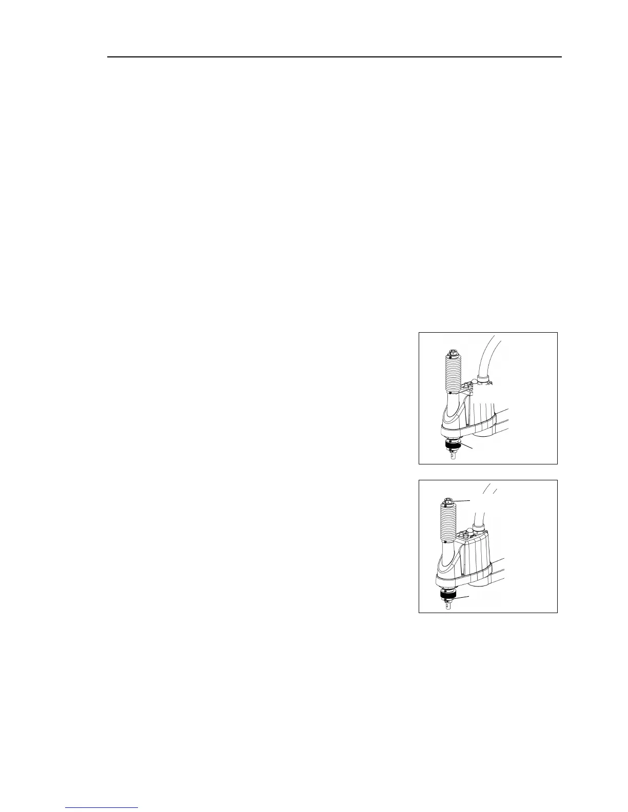
Bottom bellows
cover side
shaft edge side of the bellows.
over the bearing case (black) on the edge of
the bellows mounting part.
Then, secure them with clamp bands.
Bottom bellows
Shaft edge
completed the bellows installation, check that the bellows stretch
smoothly
without any excessive force
by moving the shaft up/down by hand and rotating
Controller and peripheral equipment.
onnect the cables and tubes to the end effector.

 Loading...


