EPSON Perfection4180 Photo Revision A
OPERATING PRINCIPLES Engine Operation Outline 20
2.1 Engine Operation Outline
This section explains the functions and operating principles of the Perfection4180
Photo Engine. The Engine is roughly divided into the Carriage Unit and Carriage
Moving Mechanism.
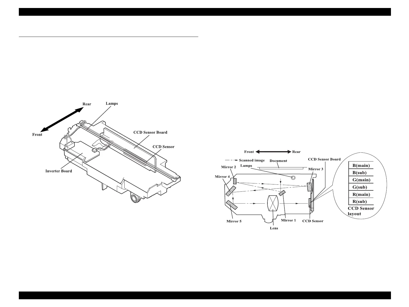
2.1.1 Carriage Unit outline
The Carriage Unit can be divided into the CCD Sensor Board, Inverter Board, Lamps
(light source), and Mirror/Lens Mechanism. (Refer to Figures 2-1, 2-2.)
Figure 2-1. Carriage Unit Configuration
CCD Sensor Board Forms an alternative six-lines color CCD (R, G, B
independent) and its control and drive circuits.
Inverter Board Boosts +24VDC and converts DC to AC to generate
the voltage for driving the Lamps (white cool cathode
fluorescent lamps).
Lamps White cool cathode fluorescent lamps are used as a
light source. When the amount of light is not stable, the
Panel LED flashes and enter the standby mode until it
becomes stable.
Mirror/Lens Mechanism The beam applied to the scanned document is reflected,
passes through the Mirror/Lens Mechanism in the
Carriage Unit for correction of the beam axis, and then
reaches the CCD Sensor. The light components R, G, B
are extracted by the Color CCD Sensor itself, not by
switching between R, G and B of the light source as
previously.
Figure 2-2. Mirror/Lens Mechanism
 Loading...