EPSON Perfection4180 Photo Revision A
DISASSEMBLY/ASSEMBLY Disassembly Procedure 41
4.2.6 Removal of Power Switch
1. Release the Carriage Lock.
(Refer to Step 1 in 4.2.3 Removal of Carriage Unit.)
2. Remove the Housing Upper.
(Refer to 4.2.2)
3. Move the Carriage Unit to the center.
(Refer to Step 3 in 4.2.3 Removal of Carriage
Unit.)
4. Disconnect the Power Switch Connector from the Main Board.
(Refer to Step 4 to
Step 7 in 4.2.5 Removal of Main Board.)
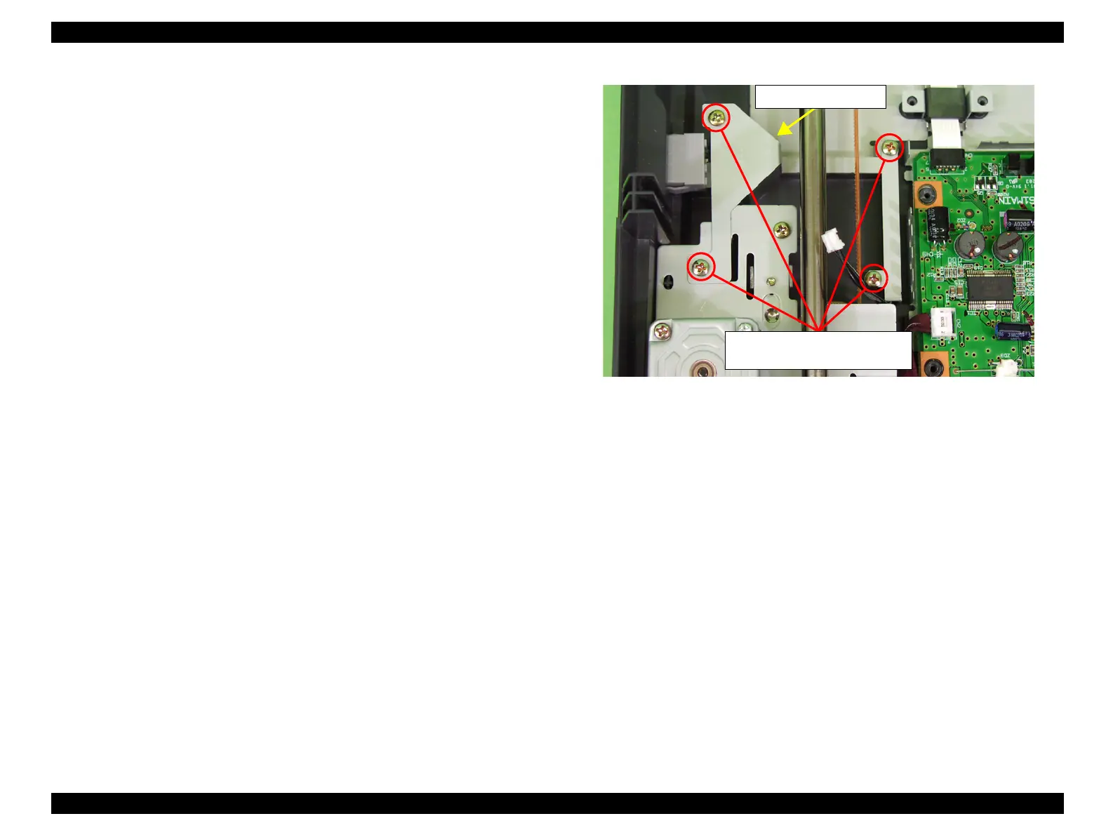
5. Remove the four screws (CBP, M3x8) that are securing the Power Cable Cover, and
remove the Power Cable Cover.
Figure 4-20. Removal of Power Cable Cover
M3x8
Tightening torque 6-8kgfcm
Power Cable Cover
 Loading...