EPSON Perfection4180 Photo Revision A
DISASSEMBLY/ASSEMBLY Disassembly Procedure 40
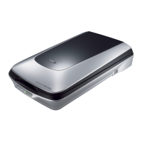
6. On the I/F side of the scanner, remove the two screws (CB SCREW, M3x8) that are
securing the Main Board, and remove the Main Board Upper Cover.
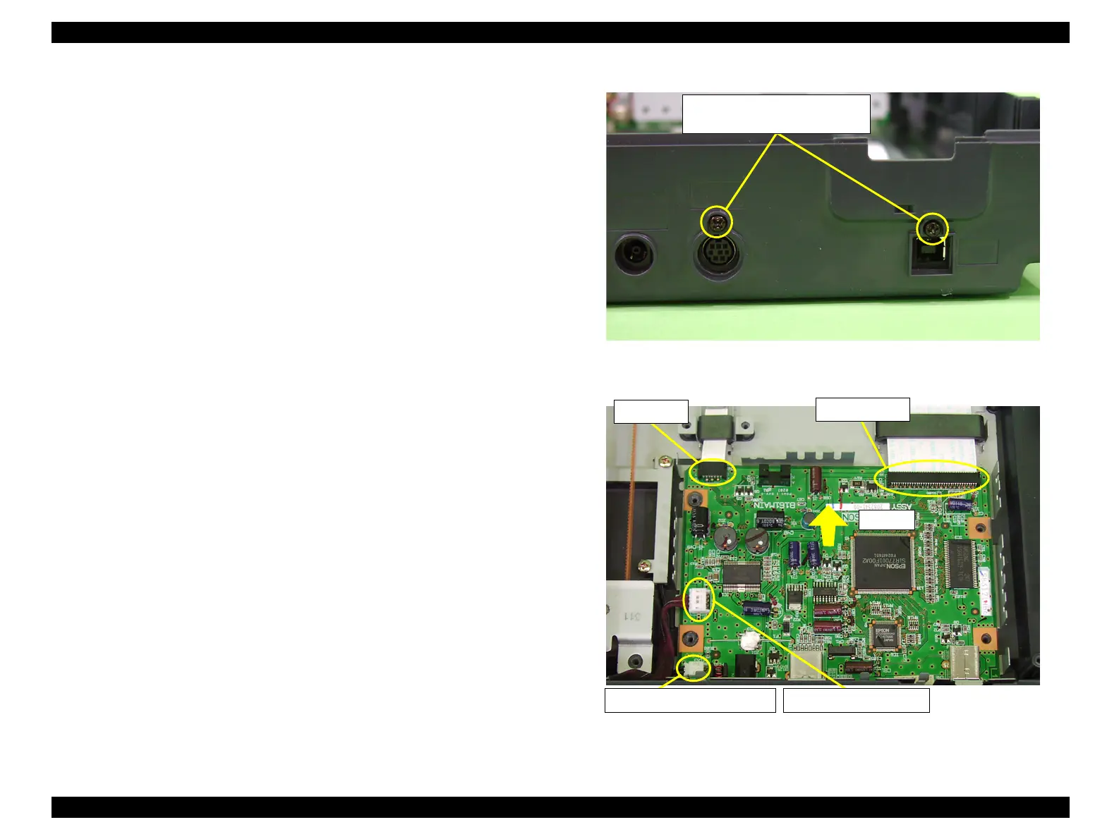
7. Lift the Main Board, disconnect all the Connectors on the Board, and remove the Main
Board.
CN1: Carriage FFC
CN2: CR Motor Connector
CN3: Power Switch Connector
CN6: Panel FFC
Figure 4-18. Removal of Main Board (1)
Figure 4-19. Removal of Main Board (2)
M3x8
Tightening torque 3-5kgfcm
Power Switch Connector
CR Motor Connector
Panel FFC
Carriage FFC
Step 7
 Loading...