EPSON Stylus C50/C60/C61/C62 Revision C
Disassembly and Assembly Disassembly 105
Fasten one screw (C.B.S. SCREW 3x6 F/Zn) for securing the
Upper power supply shield plate to the Lower power supply
shield plate. (Refer to Figure 4-26)
Tightening torque for screw is as follows.
•
C.B.S. SCREW, 3x6, F/Zn (1 pcs) : 6 ± 1 kgf.cm
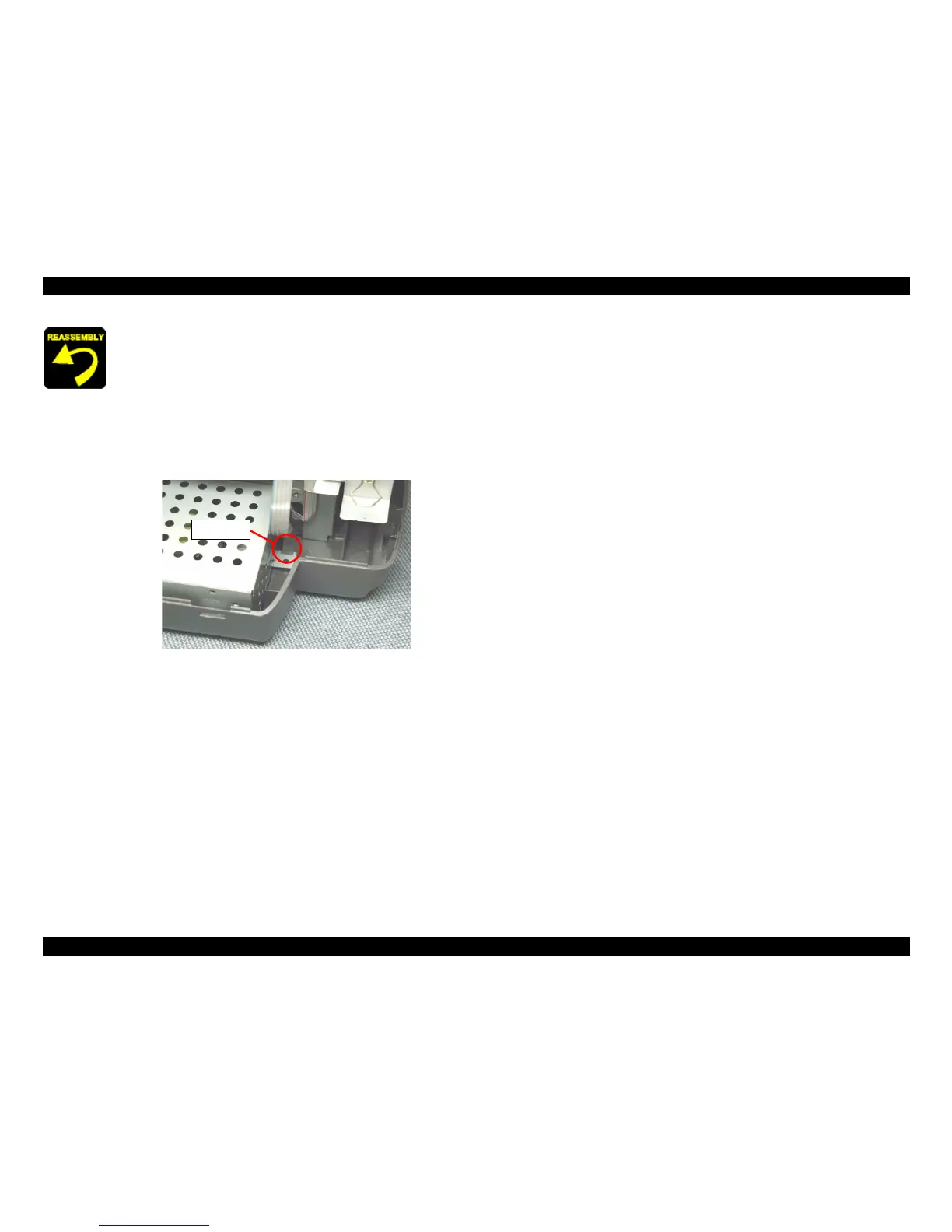
When assembling the PSB/PSE unit to the Lower housing,
Make sure to set the PSB/PSE unit under the protrusion of
the Lower housing.
Figure 4-30. Power supply board shield plate setting position
Make sure to connect the Power supply connector cable to
the connector (CN2) on the Main board.
Fasten two screws (C.B.P-TITE SCREW 3x8 F/Zn, C.B.S.
SCREW 3x6 F/Zn) for securing the PSB/PSE unit to the Lower
housing. (Refer to Figure 4-25)
Tightening torque for each screw is as follows.
•
C.B.P-TITE SCREW, 3x8, F/Zn (1 pcs) : 6 + 1 kgf.cm
•
C.B.S. SCREW, 3x6, F/Zn (1 pcs) : 6 + 1 kgf.cm
Hook
 Loading...