EPSON Stylus C67/C68/D68 Revision A
DISASSEMBLY/ASSEMBLY Disassembly Procedures 45
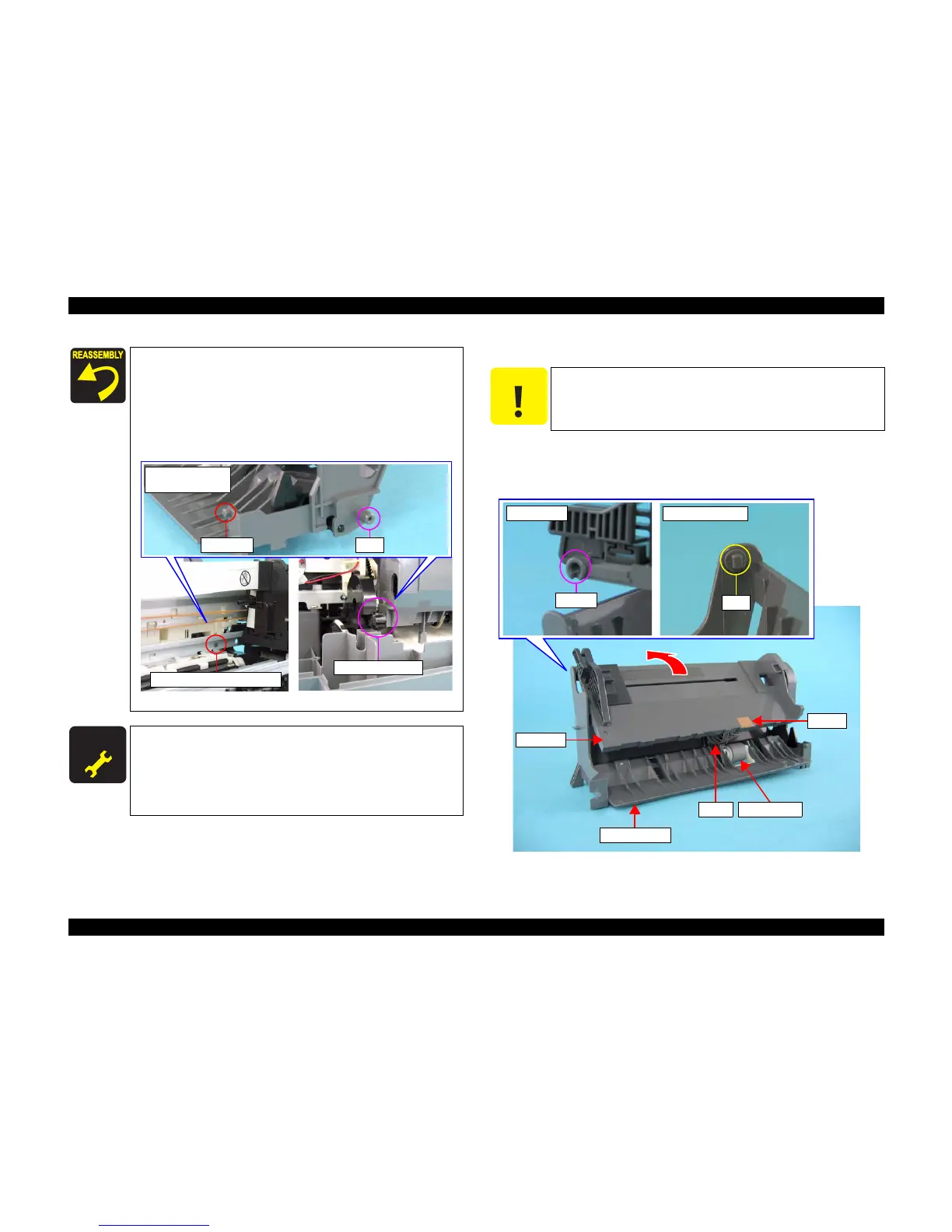
4.3.1.4 Hopper/Retard Roller Unit
1) Remove the ASF Unit. (p44)
2) Lift up the Hopper toward the direction of the arrow, release the two tabs, and
remove the spring and the hopper from the ASF Frame.
Figure 4-7. Removing Hopper
When installing the ASF Unit to the main unit, follow the steps
described below.
1. Make sure to match the guide pin of the ASF Unit with the
positioning hole of the main unit.
2. Make sure to match the shaft of the ASF Unit with the
bearing of the Pump Unit.
3. Secure the screws in the order shown in Figure 4-5.
Figure 4-6. Installing ASF Unit
A D J U S T M E N T
R E Q U I R E D
When you replace the ASF unit with a new one, lubricate it as
specified. See "6.1.3 Lubrication" (p92) for details.
When ASF unit is removed or replaced with new one, the
following adjustment must be performed in the order below.
1. “Top Margin Adjustment”
2. “First Dot Adjustment”
Shaft and Bearing
Guide Pin and Positioning Hole
Side Surface of the
ASF Unit
Guide Pin
Shaft
C A U T I O N
Do not touch the cork on the Retard Roller and the Hopper.
Spring
Hopper
Retard Roller
Cork
Hopper Side
Tab
ASF Frame Side
Shaft
ASF Frame

 Loading...


