EPSON Stylus C67/C68/D68 Revision A
DISASSEMBLY/ASSEMBLY Disassembly Procedures 46
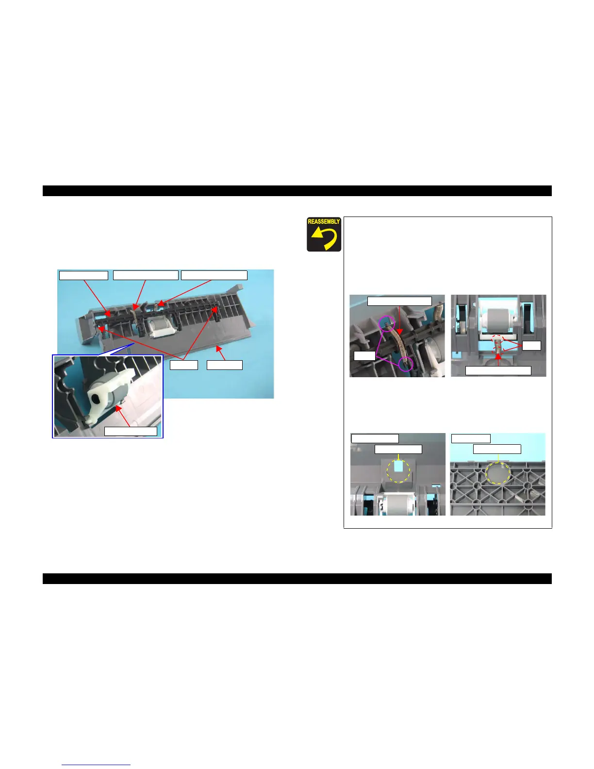
3) Remove Extension Spring 0.585 from both the ASF Frame and the Paper back
Lever.
4) Remove the Paper Back Lever from the bearing of the ASF frame.
5) Remove Compression Spring 1.88 from the ASF Frame, and remove the
Retard Roller Unit.
Figure 4-8. Removing Retard Roller Unit
Paper Back Lever
Retard Roller Unit
Compression Spring 1.88Extension Spring 0.585
Bearing ASF Frame
When installing the Retard Roller or the Paper Back Lever,
attach the two springs as described below.
• Extension Spring 0.585
Attach the spring to the tab of the ASF Frame and the one of
the Paper Back Lever.
• Compression Spring 1.88
Attach the spring to the boss of the ASF Frame and the one
of the Retard Roller Unit.
Figure 4-9. Attaching the Springs
When installing the spring between the Hopper and the ASF
Frame, match the spring with the positioning hole (circular
dent) of the Hopper and the one of the ASF Frame.
Figure 4-10. Attaching the Springs
Tabs
Extension Spring 0.585
Compression Spring1.88
Bosses
ASF Frame Side
Positioning Hole
Hopper Side
Positioning Hole

 Loading...


