EPSON Stylus C67/C68/D68 Revision A
DISASSEMBLY/ASSEMBLY Disassembly Procedures 49
To ensure the assembling accuracy, you have to control the
assembled standard position of the Main Frame against X/Y/Z-
axis direction as follows.
[X-axis direction]
• Make sure that main frame is correctly placed on the
groove of Housing (Lower).
• Make sure that there is no gap between main frame and
Housing (Lower).
[Y-axis direction]
• Make sure that cut-out portion of main frame is correctly
placed on the square protrusion of Housing, Lower.
Figure 4-16. X and Y-axis Assembled Standard Position
X-axis Assembled Standard Position
Y-axis Assembled Standard Position
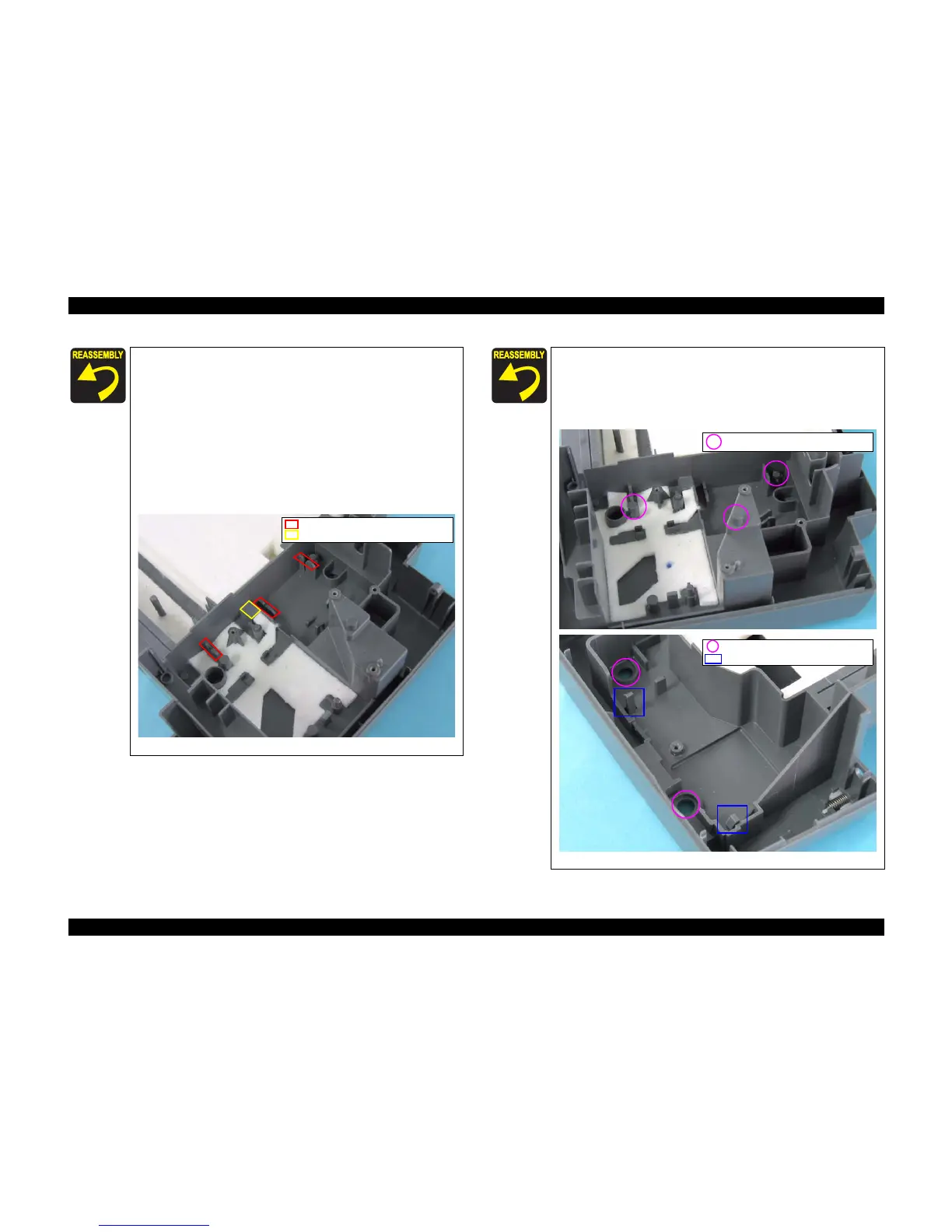
[Z-axis direction]
• Make sure that there is no gap between main frame and
Housing, Lower.
• Make sure that the left side of Printer Mechanism is
correctly fixed with two tabs.
Figure 4-17. Z-axis Assembled Standard Position
Z-axis Assembled Standard Position
Z-axis Assembled Standard Position
Tabs

 Loading...


