EPSON Stylus C67/C68/D68 Revision A
DISASSEMBLY/ASSEMBLY Disassembly Procedures 50
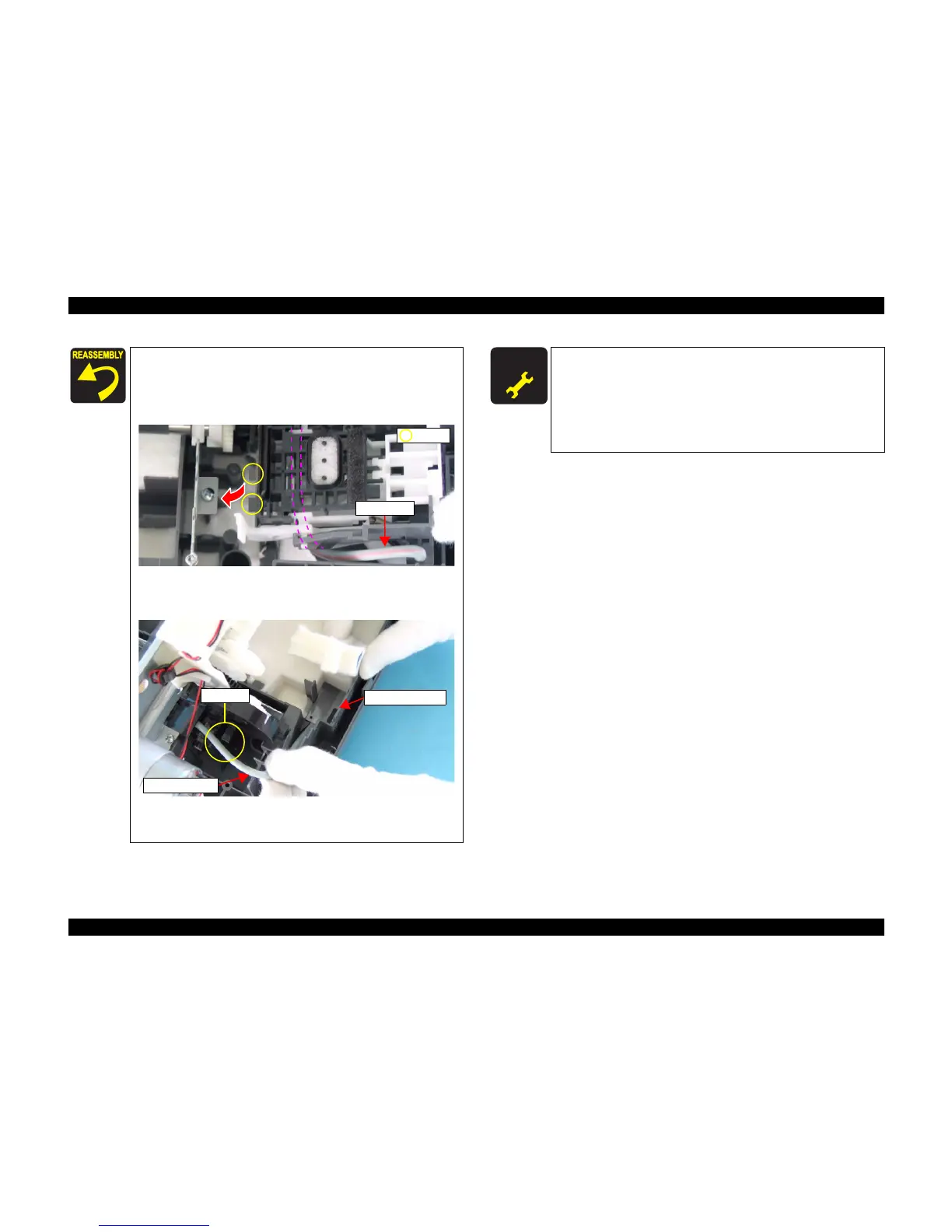
When installing the Cap Unit, pay attention to the following
instructions:
• Route the Ink Tube underneath the Cap Unit.
• Make sure that the two bosses of the Cap Unit are located
under the Main Unit Frame.
Figure 4-18. Installing Cap Unit
When installing the Cap Unit, route the Waste Ink Tube as
shown below, and place it under the protective sheet.
Figure 4-19. Routing Waste Ink Tube
When installing the Main Frame to the Housing, Lower Assy,
secure the screws as shown in Figure 4-14.
Ink Tube
Bosses
Tab
Waste Ink Tube
Protective Sheet
A D J U S T M E N T
R E Q U I R E D
When Housing (Lower) is removed or replaced with new one, the
following adjustment must be performed in the order below.
1. “Top Margin Adjustment”
2. “PF Adjustment”
3. “Bi-D Adjustment”
4. “Head Angular Adjustment”
5. “First Dot Adjustment”

 Loading...


