EPSON Stylus C67/C68/D68 Revision A
DISASSEMBLY/ASSEMBLY Disassembly Procedures 59
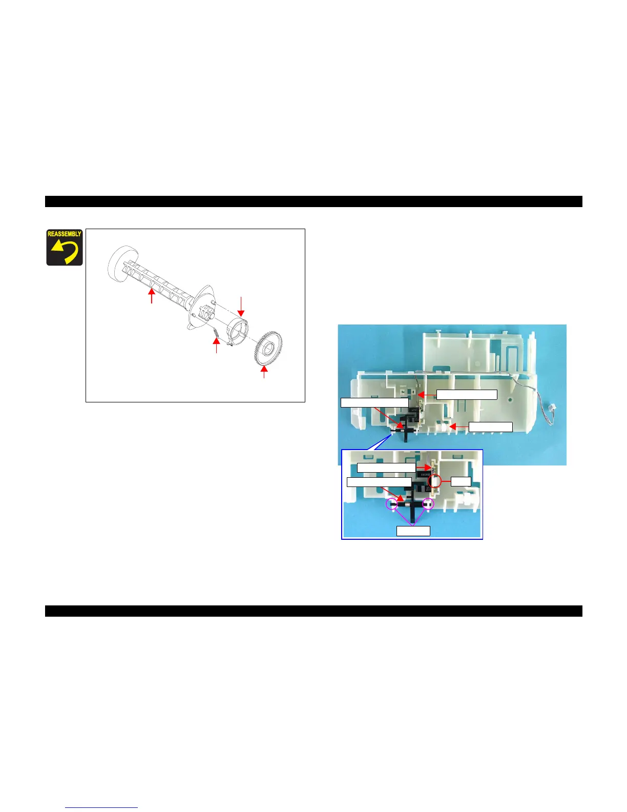
4.3.3.4 PE Sensor Board/PE Detection Lever/Idle Roller
1) Remove the Spool Gear 36.8/Extension Spring 0.143/Clutch. (p58)
2) Release the tab that secures the PE Sensor Board to the Holder Shaft Frame.
3) Release the cable from the Holder Shaft Frame, and remove the PE Sensor
Board.
4) Release the shaft of the PE Detection Lever from the bearings of the Holder
Shaft Frame, and remove Torsion Spring 0.22 from the PE Detection Lever.
5) Release the Idle Roller from the bearings of the Holder Shaft Frame.
Figure 4-39. Removing PE Sensor Board/PE Detection Lever/Idle Roller
The LD Roller Shaft Unit should be reassemble as shown below.
Figure 4-38. Assembling LD Roller Shaft Unit
Extension Spring 0.143
Spool Gear 36.8
Clutch
LD Roller
Shaft
PE Sensor Board
Torsion Spring 0.22
Bearings
Tab
PE Sensor Cable
Idle Roller
PE Detection Lever

 Loading...


