EPSON Stylus C67/C68/D68 Revision A
DISASSEMBLY/ASSEMBLY Disassembly Procedures 60
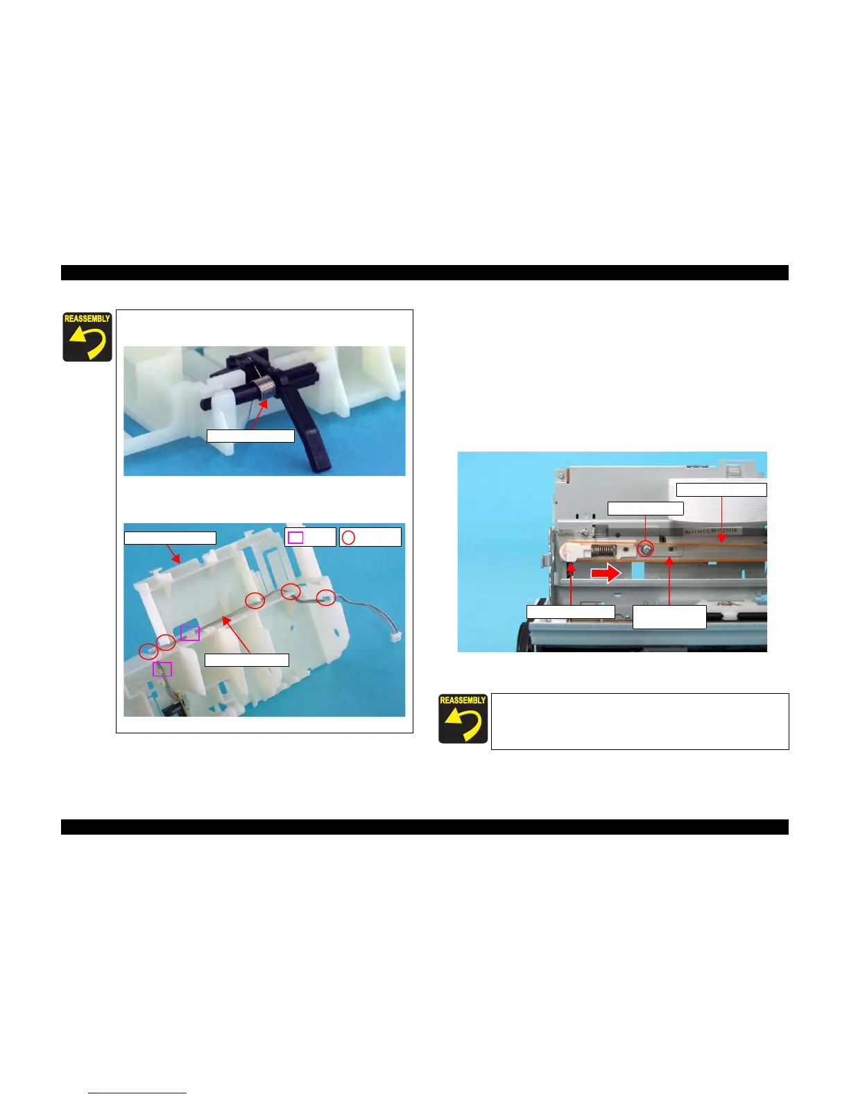
4.3.3.5 CR Timing Belt
1) Remove the Housing, Upper. (p43)
2) Move the CR Unit toward the center of the printer.
(See 4.3.3.2 Removing Holder Shaft Unit Step 3)
3) Loosen the screw that secures the Drive Pulley Holder Stopper to the Main
Unit.
• C.B.S. (P4) 3 x 6: 1
4) Press the Drive Pulley Holder toward the direction of the arrow, pull the CR
Timing Belt toward you, and remove the belt from the Drive Pulley Holder.
Figure 4-42. Removing CR Timing Belt
5) Remove the CR Unit. (p64)
When installing the PE Detection Lever, attach Torsion Spring
0.22 as shown below.
Figure 4-40. Attaching Torsion Spring 0.22
When installing the PE Sensor Cable to the Holder Shaft
Frame, route the cable as shown below.
Figure 4-41. Routing PE Sensor Cable
Torsion Spring 0.22
Tab Notch
Holder Shaft Frame
PE Sensor Cable
When installing the CR Timing Belt to the CR Unit, make sure to
attach the belt to the positioning jag as shown in Figure 4-55.
C.B.S. (P4) 3 x 6
CR Timing Belt
Drive Pulley Holder
Drive Pulley
Holder Stopper

 Loading...


