EPSON Stylus C67/C68/D68 Revision A
DISASSEMBLY/ASSEMBLY Disassembly Procedures 62
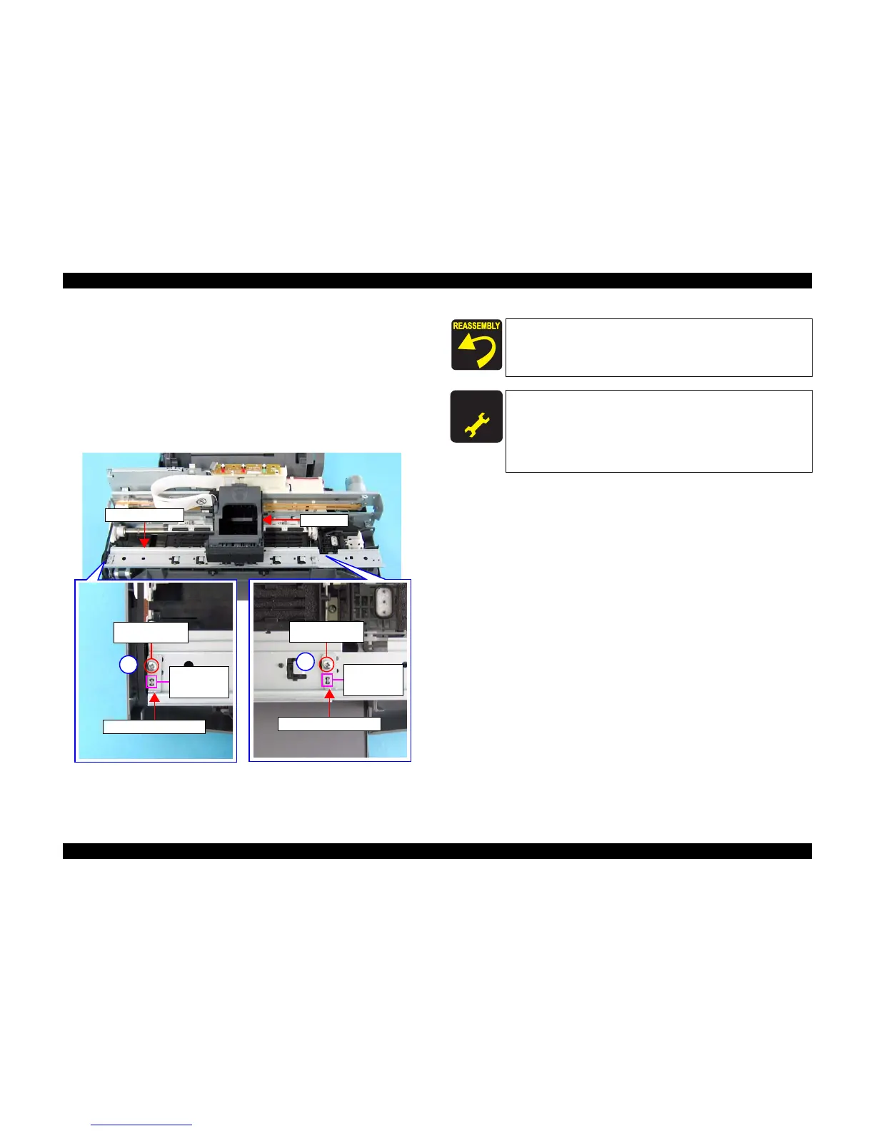
4.3.3.7 Front Frame
1) Remove the Housing, Upper. (p43)
2) Move the CR Unit to the center of the printer. (See 4.3.3.2 Removing Holder
Shaft Unit Step 3)
3) Remove both the two screws that secure the Front Frame to the Main Unit and
the Front Frame Stopper.
• C.B.S. 3 x 6: 2
4) Lift up the CR Unit, and remove the Front Frame.
Figure 4-45. Removing Front Frame
Front Frame
CR Unit
C.B.S. 3 x 6
(8
±1 kgf.cm)
1
Positioning
Hole and Rib
Front Frame Stopper
C.B.S. 3 x 6
(8
±1 kgf.cm)
2
Front Frame Stopper
Positioning
Hole and Rib
Match the positioning hole with the rib as shown in Figure 4-45
when installing the Front Frame.
Secure the screws in the order shown in Figure 4-45.
A D J U S T M E N T
R E Q U I R E D
When you replace Front frame with new one, lubricate it as
specified. See "6.1.3 Lubrication" (p92) for details.
When Front frame is removed or replaced with new one, the
following adjustment must be performed in the order below.
1. “PF Adjustment”
2. “Bi-D Adjustment”

 Loading...


