EPSON Stylus C67/C68/D68 Revision A
DISASSEMBLY/ASSEMBLY Disassembly Procedures 68
4.3.3.12 CR Encoder Sensor Board
1) Remove the CR Unit. (p64)
2) Remove the two screws that secure the CR Encoder Sensor Board to the IC
Holder, and remove the CR Encoder Sensor Board.
• C.P.B. (P1) 1.7 x 5 :2
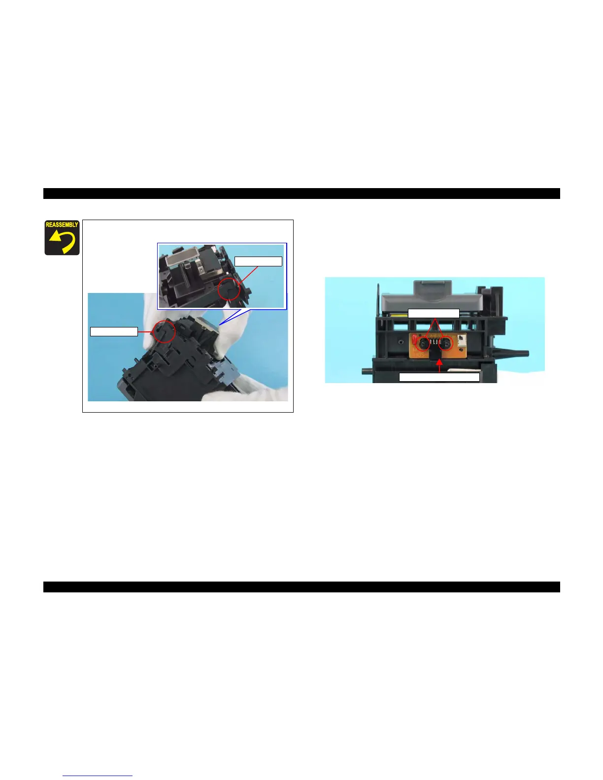
Figure 4-60. Removing CR Encoder Sensor Board
When installing the Printhead Assy. to the IC Holder, match the
tabs with the notches, and tilt the Printhead as shown below.
Figure 4-59. Installing Printhead Assy.
Tab and Notch
Tab and Notch
C.P.B. (P1) 1.7 x 5
CR Encoder Sensor Board

 Loading...


