EPSON Stylus Photo R220/R230 Revision A
DISASSEMBLY / ASSEMBLY Disassembly 57
2.3.7 Main Board Assy. Removal
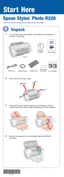
External View
Figure 2-15. Main Board Assy. Removal
Parts/Units which should be removed before removing Main Board Assy.
Paper Support Assy./Housing (left/right)/Housing, Frame/ASF Assy.
Disassembly Procedure
1. Remove the screw that secures the Earth and release the Earth.
2. Disconnect the all connector cables from the Main Board and remove the
Acetate Tapes from the Main Board.
CN2 : Power Supply cable
CN6 : PF Motor cable
CN13 : APG Motor cable
CN10 : Interface Board cable
CN7 : Print Head FFC
CN8 : Print Head FFC
CN15 : CSIC/CR Encoder /PW Sensor FFC
CN5 : CR Motor cable
CN9 : PE Sensor cable
3. Remove the two screws that secure the Main Board Assy., and remove it.
4. Remove the Shield Plate, FFC from the M/B Mounting Plate.
5. Remove the three screws that secure M/B Shield Plate, and remove the M/B
Shield Plate and the Main Board from the M/B Mounting Plate.
C.B.S. 3x6 (5-7kgf.cm)
C.B.S. 3x10 (5-7kgf.cm) Main Board
3
M/B Shield Plate
2
1
Shield Plate, FFC
Front of the Printer
C.B.S. 3x4 (5-7kgf.cm)
Rear of the Printer
M/B Shield Plate
Step 3
C.B.S. 3x6 (5-7kgf.cm)
Earth
Step 1
Step 3
M/B Mounting
When reinstalling the Main Board Assy.,
Make sure that all connector cables (CN2, CN6, CN13,
CN10, CN7, CN8, CN15, CN5, CN9) are correctly connected.
Tighten the three screws to secure the M/B Shield Plate in
the order shown in Figure2-15.
A D J U S T M E N T
R E Q U I R E D
When having replaced the Main Board, perform the following
operations and adjustments.
(Refer to Chapter 3 “ADJUSTMENT”)
When possible to read data from the old board, copy the
EEPROM data after replacing the old board with a new one.

 Loading...