2-10 Setup Rev. A
2.4.1.3 Connecting the serial interface (RS-232) cable
WARNING:
Be sure to turn off the power supply for both the printer and host computer before
connecting the cables.
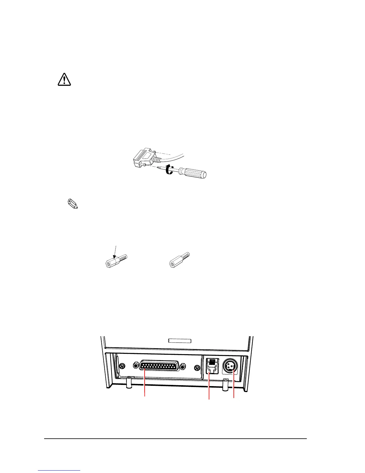
1. Insert the interface cable connector firmly into the interface connector on the connector
panel.
2. When using connectors equipped with screws, tighten them to secure the connectors firmly.
Figure 2-7 Tighten screws
Note:
The printer comes with hex-head screws with inch-threaded holes installed. When using an interface
cable with metric-thread screws, use a hexagonal screwdriver (5 mm) to replace the installed screws
with hex-head screws with metric-threaded holes, also supplied.
Figure 2-8 Hex-head screws threaded in inches and millimeters
3. When using interface cables equipped with a ground line, attach the ground line to the
screw hole marked “FG” on the printer.
4. Connect the other end of the interface cable to the host computer.
Figure 2-9 Printer connectors
Identified by encircling line mark
Metric-threaded hole
Inch-threaded hole
DK
DC24V
FG
FG
Interface connector
Drawer kick-out connector
Power supply connector
 Loading...