6 • Circuit Descriptions
22 / 56
80116-261
2018-07
Description of the various assemblies
Line input
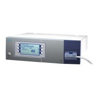
The EIP 2 can be operated on line voltages of 230 V, 120 V, or 100 V. First
of all the appropriate figure must be set, ±10
%, in the window of the volt-
age selector switch on the main board.
Transformer
The transformer converts the line voltage input from 230 V ±10 % or
120
V ±10 % to 2 x 9 V. The maximum available current is 1.33 A.
For operation of the EIP 2 at a line voltage of 100 V ±10 % a different type
of transformer must be used. That transformer converts the line voltage
input to 2 x 12
V um. The maximum available current is 1.25 A.
Bridge-connected rectifier
The bridge-connected rectifier provides the operating voltage of 24 V.
Switching controller
The switching controller provides an operating voltage of 5 V.
Monitoring the motor control
This circuit is designed to prevent a faulty motor control from leading to
uncontrolled pump activity. The operating voltage of 24
V is only supplied
to the motor control if the microcontroller releases it by actuating the
monitoring circuit accordingly.
Motor control
The motor control is regulated by the microcontroller via a PWM signal at
a level of 5
V. The output voltage of the motor control is increased to a
maximum of 24
V depending on the PWM signal.
CAUTION! An incorrect setting can cause damage to the unit.