EASY-ROTOR-CONTROL M V2.2 Instructions
___________________________________________________________________________
© Ing.-Büro E. Alba de Schmidt web : www.schmidt-alba.de
Tannenstr. 16 Page 18 of 44 email : erc@schmidt-alba.de
86836 Untermeitingen / Germany
This document is for the user only. Any publishing (printed or in electronic form) is not allowed.
3. LAN-Interface (optional)
3.1 Bill of material
The BOM is in the order how you should use the parts.
ERC-M V2.0 LAN Bill Of Material
QTY
Type Value Reference
Comments
1
Diode 1N4004 D12 alt. 1N4007
2
Capacitor ceramic 100n 50V 20%
C15,C16
1
Capacitor Tantal 1u 35V 20% C23
2
Resistor 10K 5% R1,R12 alt. 10K 1%
1
Diode BAT48 D7
1
XPORT 1001001-04R XP1 alt. 1001000-04R
1
DC/DC 12V 3.3V 1W DC1
1
Patchcable 2m Crossover
3.2 Assembly of the LAN-Interface
Assemble and solder the components according to the following drawings. The components to be
assembled are marked blue in the following drawings.
Please read the following instructions before you start:
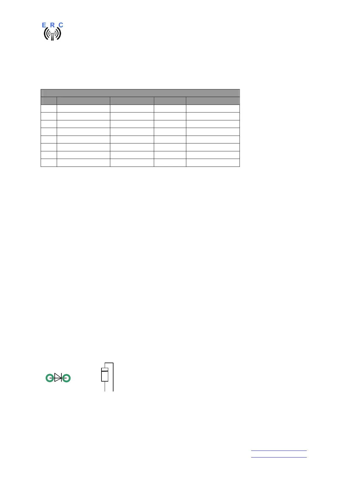
1. The vertical assembled Diodes should have a distance (1-2mm) to the PCB while soldering.
Otherwise there is the risk of overheating these components while soldering.
2. Take care of polarization of the following components :
- Diode D7,D12
- DC/DC DC1
- Capacitor tantal C23
Those components are marked red in the following drawing.
It is important to solder the ground-lugs of the XPORT properly as they are used for heat-dissipation
from the XPORT to the printed board.
Components :
Colour-code of Resistors:
10K 5% brown-black-orange-gold
alt.: 10K 1% brown-black-black-red-brown
Diodes :
=