EASY-ROTOR-CONTROL M V2.2 Instructions
___________________________________________________________________________
© Ing.-Büro E. Alba de Schmidt web : www.schmidt-alba.de
Tannenstr. 16 Page 8 of 44 email : erc@schmidt-alba.de
86836 Untermeitingen / Germany
This document is for the user only. Any publishing (printed or in electronic form) is not allowed.
So fare, don’t put the ICs (MEGA328, USB-Module and ULN2003) into their sockets.
First a little electrical test should be performed:
1.4 Connection of the DC-supply and check of the voltage-regulator
Now put the jumper on the 1x2 pinheader JP1 (the jumper supplies the ERC with +5V).
After checking all assembled components for identity, polarization and solder-bridges, prepare a DC-
cable with 10 to 15VDC by using the DC-connector supplied with the kit or use any other DC-supply
with that voltage and an appropriate DC-Connector of 2.1/5.5mm.
Connect the Plus(+)-pole to the center contact
and the Minus(-)-pole to the outer contact.
Before connecting the DC-connector to the
ERC-M, measure the voltage at the connector,
if it is in the range needed.
If DC is reversed, nothing will happen as the
Circuit is proven against wrong polarization.
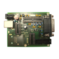
Now plug the DC-connector into J1 of the ERC-M. After connecting DC correctly, you should
measure +5VDC +/-0.2V at the test-point +5V and +10 to +15VDC at test-point +12V against GND.
Disconnect the supply now.
Testpoint +5V Testpoint +12V
GND