EASY-ROTOR-CONTROL M V2.2 Instructions
___________________________________________________________________________
© Ing.-Büro E. Alba de Schmidt web : www.schmidt-alba.de
Tannenstr. 16 Page 4 of 44 email : erc@schmidt-alba.de
86836 Untermeitingen / Germany
This document is for the user only. Any publishing (printed or in electronic form) is not allowed.
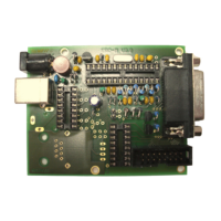
1.2 Preparation of USB-modul
Solder the 8-pin pin-header 90° to the bottom side of the USB-module. Take care, that the shorter side
of the pins is soldered to the USB-Module.
1.3 Assembly of the ERC-M USB PCB
Assemble and solder the components according to the following drawings.
Please read the following instructions before you start:
1. The vertical assembled Diodes should have a distance (1-2mm) to the PCB while soldering.
Otherwise there is the risk of overheating these components while soldering.
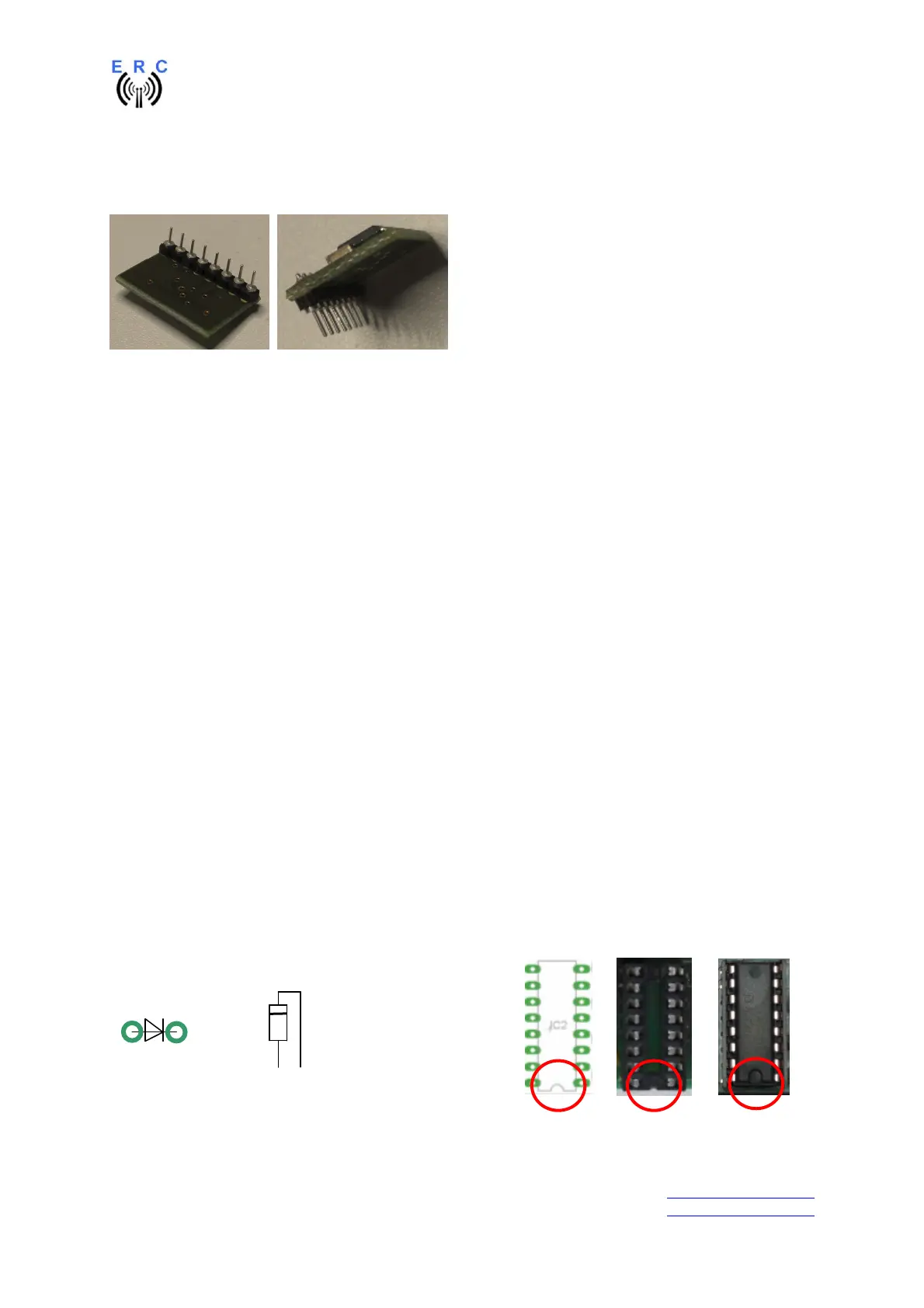
2. Take care of polarization of the following components (marked red in the assembly drawing):
- Diodes D1,D2,D3,D4,D5,D6,D8,D9,D10,D11,D13,D14
- Capacitor electrolytic C5
- Capacitor tantal C7,C8
- IC-socket for IC1,IC2,IC3
- Transistor T1,T2
- Voltage-regulator IC4
- Box-header X3
3. Carefully compare the position of the PCB with the drawings before you start to assemble it.
Components:
Colour-code of Resistors:
4K7 5% yellow-violet-red-gold
alt.: 4K7 1% yellow-violet-black-brown-brown
20K 5% red-black-orange-gold
alt.: 20K 1% red - black-black-red- brown
39K 5% orange-white-orange-gold
alt.: 33K 1% orange-white- black-red-brown
220K 5% rot-rot-yellow-gold
alt.: 220K 1% rot-rot- black-orange-brown
Colour-code of Coils:
10uH 10% brown-black-black-silver
Diodes : ICs and sockets
=