EASY-ROTOR-CONTROL M V2.2 Instructions
___________________________________________________________________________
© Ing.-Büro E. Alba de Schmidt web : www.schmidt-alba.de
Tannenstr. 16 Page 25 of 44 email : erc@schmidt-alba.de
86836 Untermeitingen / Germany
This document is for the user only. Any publishing (printed or in electronic form) is not allowed.
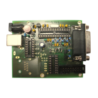
Check carefully the assembly. So, this is how it should look like.
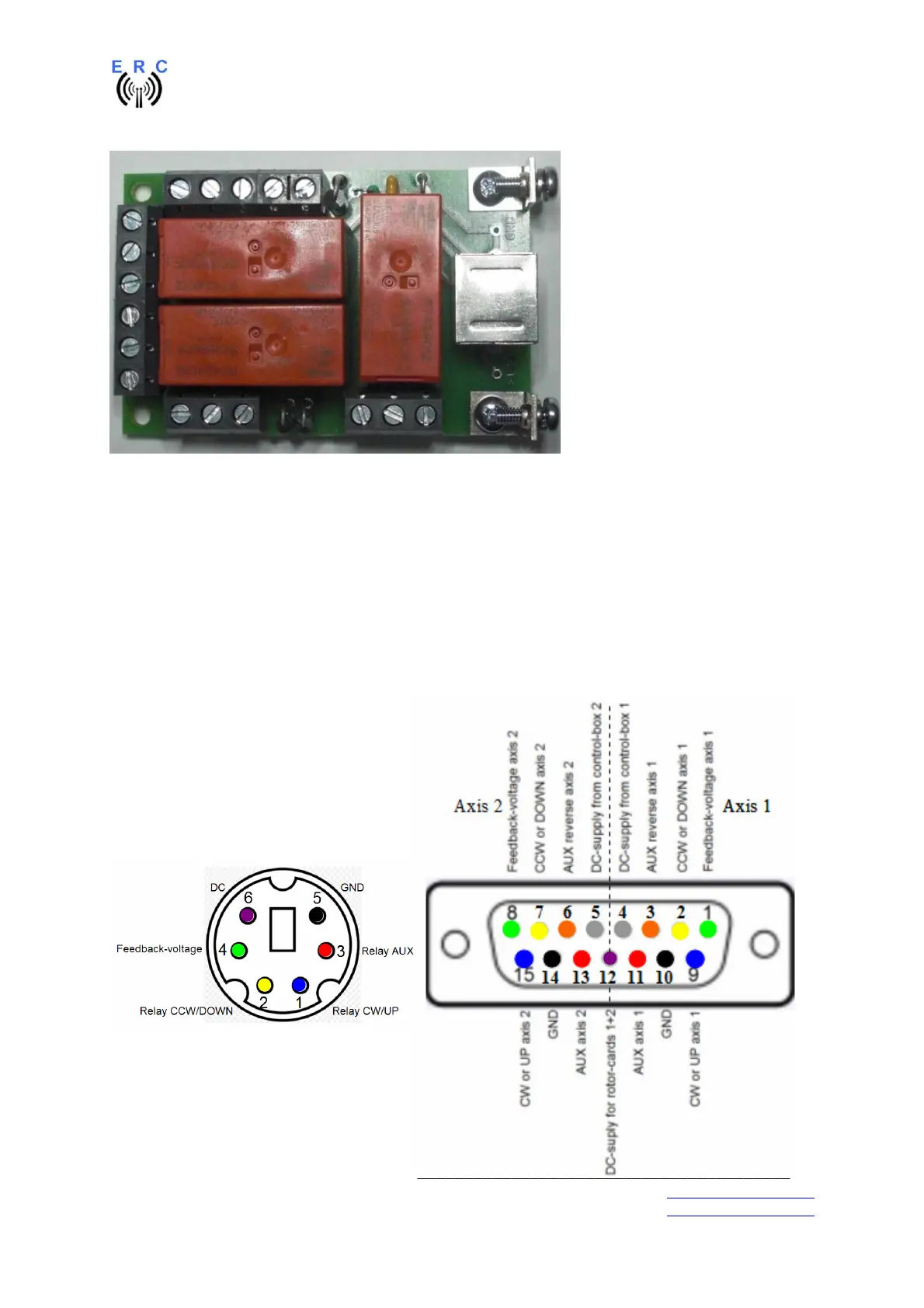
4.3 Connection of the Rotor-Card
The connection between Rotor-Card and ERC-M has to be done with the 6-pin Mini-DIN-cable
supplied with the Rotor-Card-kit. The connections are shown in the next picture. Connect the pins with
the same colour between the Mini-DIN-connector and the D-SUB-connector for axis 1 or axis 2.
1 or 2 rotators can be connected to ERC-M.
- In an AZ/EL-configuration connect AZ to axis 1 and EL to axis 2.
- If you only use 1 rotator, use axis 1.
Connector of ERC-M seen from outside
Connector of Rotor-Card seen from outside