EASY-ROTOR-CONTROL M V2.2 Instructions
___________________________________________________________________________
© Ing.-Büro E. Alba de Schmidt web : www.schmidt-alba.de
Tannenstr. 16 Page 39 of 44 email : erc@schmidt-alba.de
86836 Untermeitingen / Germany
This document is for the user only. Any publishing (printed or in electronic form) is not allowed.
8. Theory of operation
A Microcontroller receives commands via the RS232- or USB or LAN-interface in the Yaesu GS-232B
(or GS-232A) or DCU-1 protocol from the programs that support controlling rotators.
The ERC-M takes the task to move the rotator to the desired position or to stop the rotator while it is
moving. Also changes of the direction are possible while the rotator is moving. The current position of
the rotators is calculated from the measured rotor-feedback-voltages AZ and EL. To achieve accurate
function, the ERC-M has to be calibrated to the specific value of the rotor-feedback-voltages (ref. to
the next chapter).
Depending on the direction to move, the contacts CW and CCW or UP and DWN are tighten to
ground. With a programmable delay the contact AUX1 and AUX2 will be activated to control the speed
or the brake of the rotator.
The ERC-M is powered either the USB-bus, by the control-box it is connected to or by external
10..12VDC. The current consumption is according to the USB-specifications. Using an USB-hub may
require to power this hub. Wherever there is a suitable DC-supply available on the rotor-controllers
remote-jack, it is taken from there to supply the ERC-M. The ERC-M is than switching automatically to
the external supply in order not to drawn current from the USB-bus.
9. Calibration
After the ERC-M is connected to the rotor-controller, it has to be calibrated. This calibration is needed,
because different kinds of rotators deliver different kinds of feedback-voltages. Also variations
between rotators of the same model would lead to inaccuracy. To calibrate the ERC-M, it has to
measure the rotor-feedback-voltages at both ends including overlaps (turning radius > 360°). The
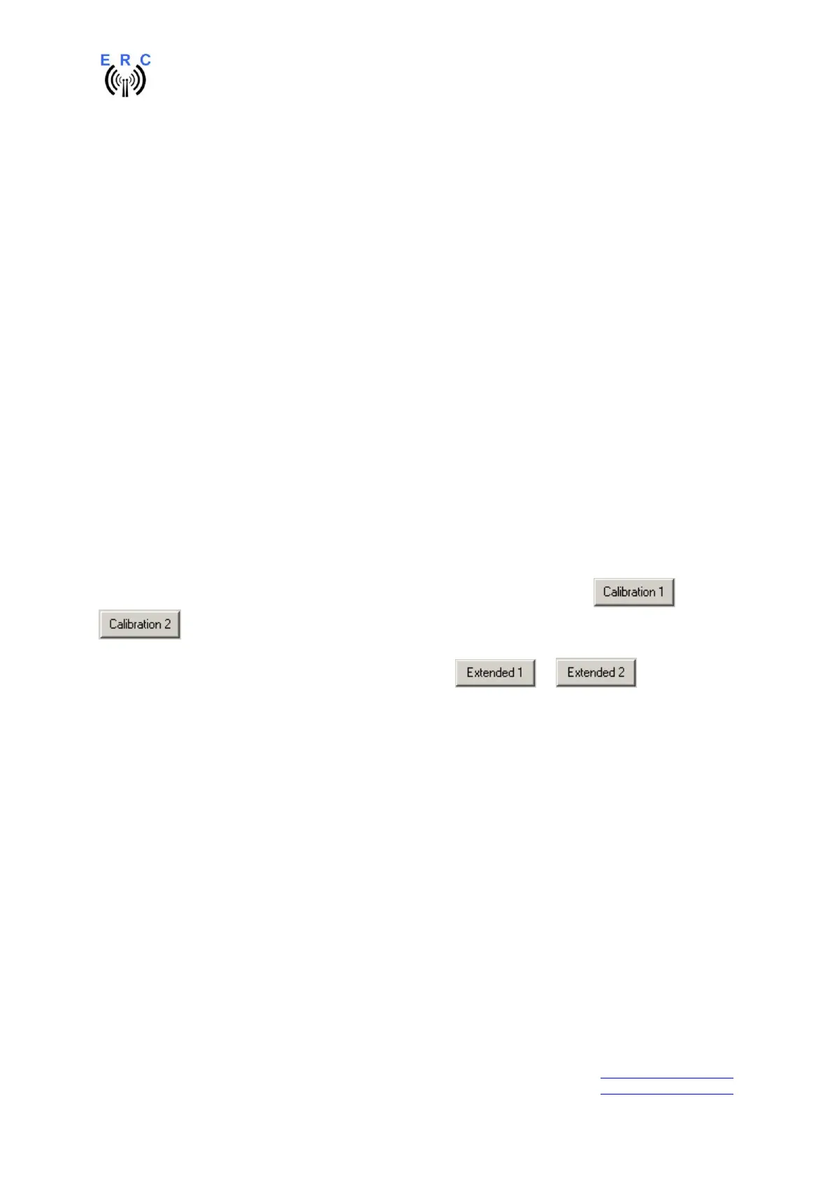
calibration is a software-guided procedure, which will be started by pressing the or
button of the service tool. Just follow the instructions given by the calibration assistant.
If the feedback-voltage of the rotator has unlineraities, an extended calibration can be performed every
30° for azimuth or every 15° for elevation by pressing the or button.
10. First check of calibration with Rotor-Control M
The rotor-control-program Rotor-Control M is on the CD supplied with the kit.
Start the Setup-File SETUP RC-M_Vnn.EXE directly on the CD and follow the instructions.
The installation wizard will automatically install the Service Tool in the program directory (or any other
if you choose a different one) and puts an icon on your desktop.
Set the ERC-M with the Service-Tool to Baudrate 9600 and Protocol GS232B.
Start Rotor-Control M by double-clicking the Icon on the desktop.
The green pointers and numbers show the current position of the rotators.
Targets can be put at the red numbers.
You can control the rotators for Azimuth and Elevation separately or together. Click the GO- or STOP-
buttons.
You can also move a rotator to a target-position by clicking on any point of the graphics.
By clicking the button PARK, the rotators move to their configured parking positions.