EASY-ROTOR-CONTROL M V2.2 Instructions
___________________________________________________________________________
© Ing.-Büro E. Alba de Schmidt web : www.schmidt-alba.de
Tannenstr. 16 Page 30 of 44 email : erc@schmidt-alba.de
86836 Untermeitingen / Germany
This document is for the user only. Any publishing (printed or in electronic form) is not allowed.
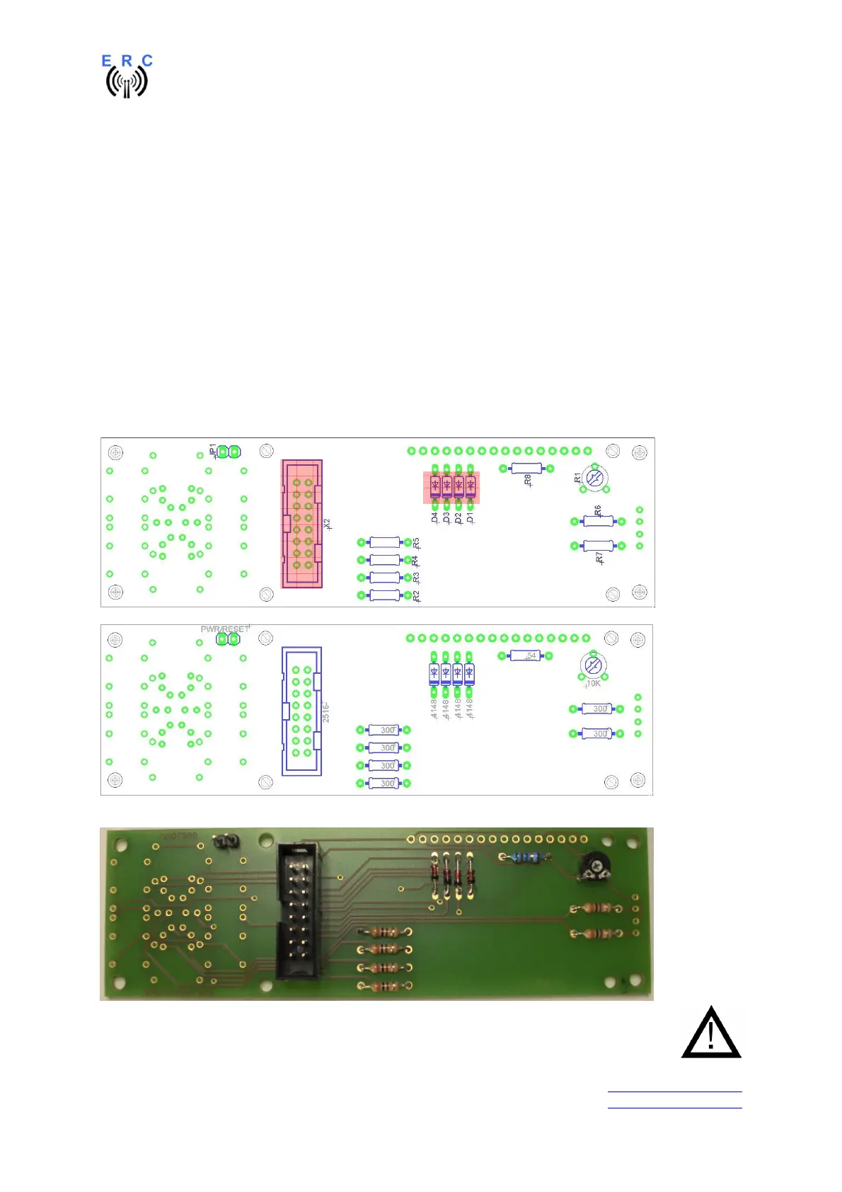
6.2 Assembly of bottom-side HID-PCB
Assemble and solder the components according to the following drawings.
Please read the following instructions before you start:
Take care of polarization of the following components:
- Diodes D1,D2,D3,D4
- Box-header X2
Those components are marked red in the following drawing.
Carefully compare the position of the PCB with the drawings before you start to assemble it.
Components :
Colour-code of Resistors:
54R 5% green-yellow-black-gold
alt.: 53.6R 1% green-orange-blue-gold-brown
300R 5% orange-black-brown-gold
alt.: 300R 1% orange-black-black-black-brown
This is how it should look like:
Inspect carefully the assembly and soldering. Once the LCD is mounted (next step),
it becomes quite difficult to rework any soldering or assembly of the bottom-side !