EASY-ROTOR-CONTROL M V2.2 Instructions
___________________________________________________________________________
© Ing.-Büro E. Alba de Schmidt web : www.schmidt-alba.de
Tannenstr. 16 Page 41 of 44 email : erc@schmidt-alba.de
86836 Untermeitingen / Germany
This document is for the user only. Any publishing (printed or in electronic form) is not allowed.
Appendix
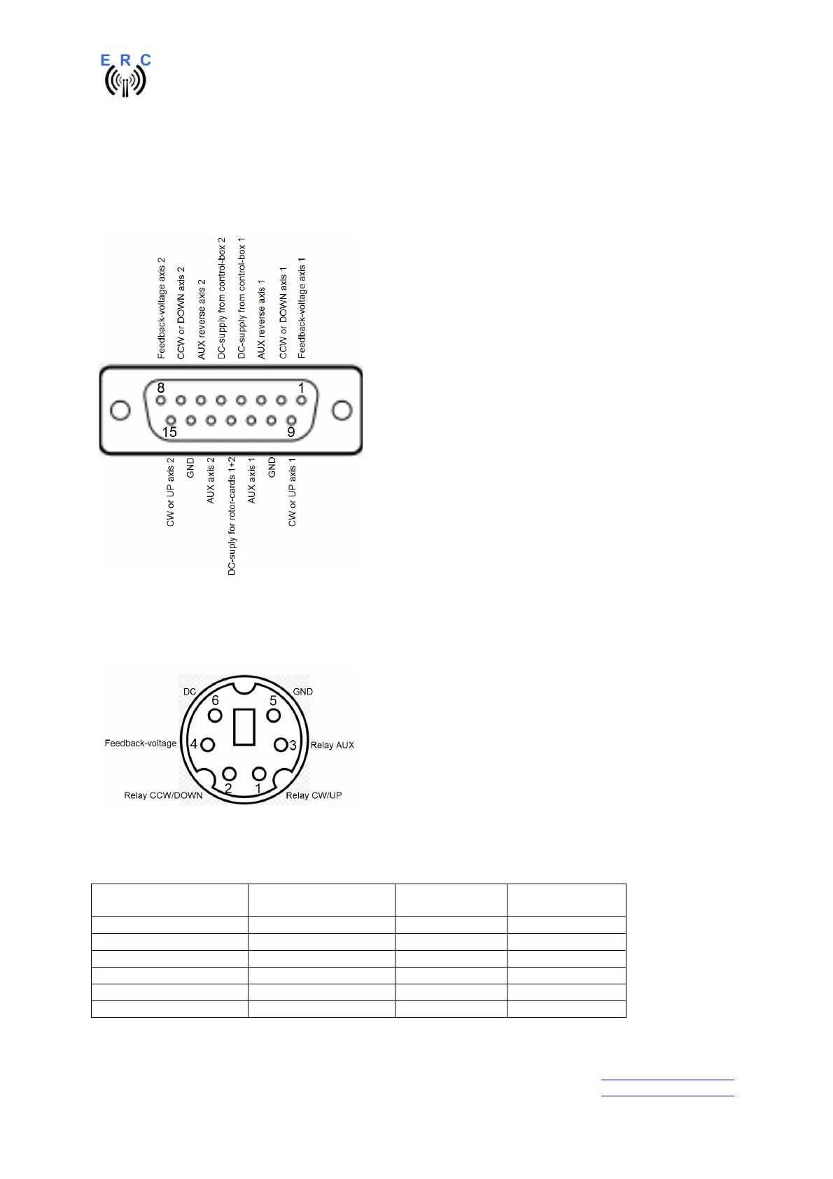
Appendix1: Pin-out of D-SUB15 ERC-M
Connector seen from outside to the female connector on ERC-M or on the back of the desktop-
housing.
Appendix2: Pin-out of mini-DIN rotor-card
Connector seen from outside to the female connector on the rotor-card.
Appendix3: Connection of rotor-card to ERC-M
Mini-DIN rotor-card Signal D-SUB ERC-M
axis 1
D-SUB ERC-M
axis 2
1 CW/UP 9 15
2 CCW/DOWN 2 7
3 AUX 11 13
4 Feedback-voltage 1 8
5 GND 10 14
6 DC-supply 12 12