EASY-ROTOR-CONTROL M V2.2 Instructions
___________________________________________________________________________
© Ing.-Büro E. Alba de Schmidt web : www.schmidt-alba.de
Tannenstr. 16 Page 33 of 44 email : erc@schmidt-alba.de
86836 Untermeitingen / Germany
This document is for the user only. Any publishing (printed or in electronic form) is not allowed.
6.4 Assembly of top-side HID-PCB AZ/EL (azimuth&elevation)
If your housing is AZ/AZ (dual azimuth) go back to step 6.3
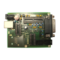
First assemble the LCD with the 5mm spacers, screws, nuts and spring-washers to the PCB. Put the
16-pole pin-header between PCB and LCD before mounting. Leave the protection-foil on the LCD until
the HID will be mounted into the housing.
Now solder the 16-pole pin-header first to the LCD and than to the PCB.
This is how it should look like:
Please read the following instructions before you proceed:
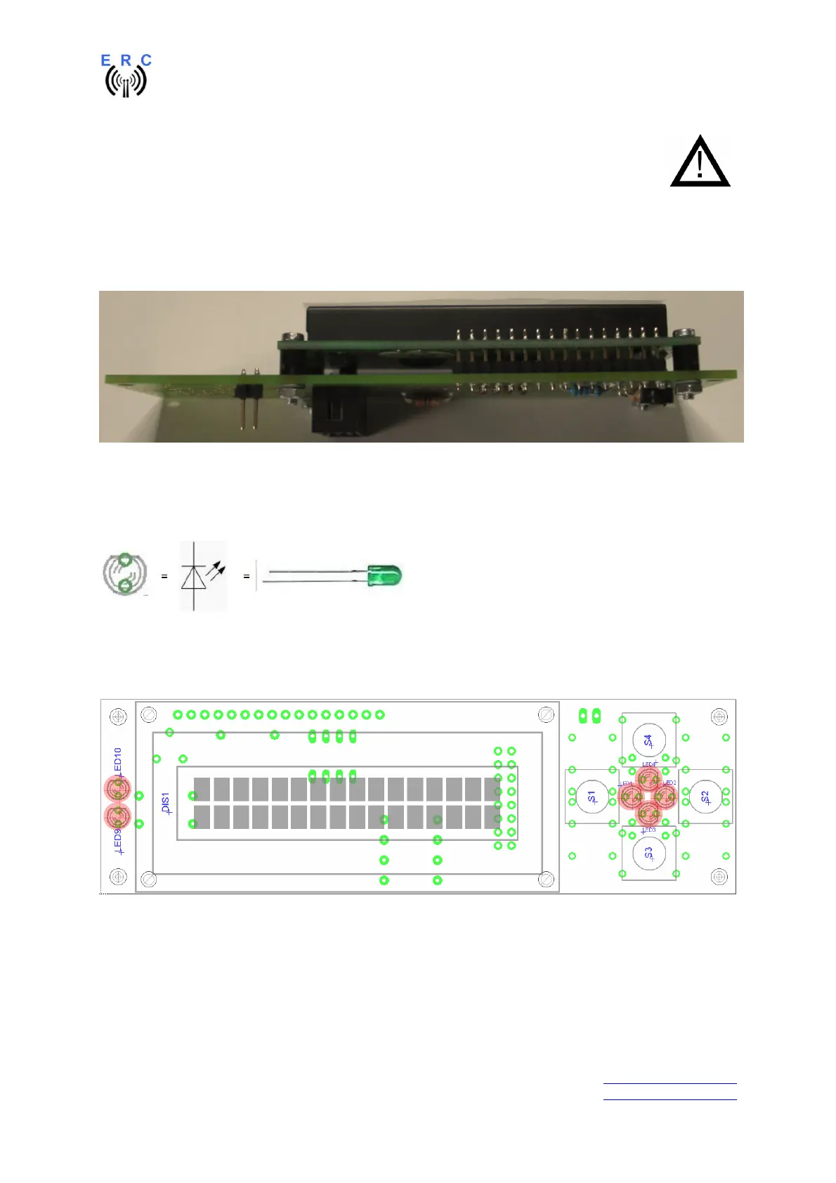
LEDs:
Take care of polarization of the following components :
- LED1,LED2,LED3,LED4,LED9,LED10
Those components are marked red in the following drawing.
Assemble and solder the switches and LEDs according to the following drawings.
Take care that the switches fit plane to the PCB. Otherwise you will have problems with sticky
switches later when the HID is mounted to the front-panel.
Hint: Only solder 1 leg of the switches and LEDs, check for alignment and than solder the remaining
pins.
long leg
short leg
flat side
round side