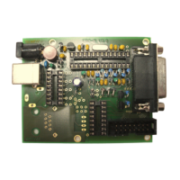
EASY-ROTOR-CONTROL M V2.2 Instructions
___________________________________________________________________________
© Ing.-Büro E. Alba de Schmidt web : www.schmidt-alba.de
Tannenstr. 16 Page 1 of 44 email : erc@schmidt-alba.de
86836 Untermeitingen / Germany
This document is for the user only. Any publishing (printed or in electronic form) is not allowed.
Instructions
Congratulations for buying your EASY-ROTOR-CONTROL M (shortly ERC-M). This
document will guide you through the needed steps for assembly and configuration of
the ERC-M. You will reach the best result by following these instructions step by step.
Table of contents
Safety-Instructions ................................................................................................................. 2
1. ERC-M USB ...................................................................................................................... 3
1.1 Bill of material (BOM)................................................................................................. 3
1.2 Preparation of USB-modul........................................................................................... 4
1.3 Assembly of the ERC-M USB PCB............................................................................. 4
1.4 Connection of the DC-supply and check of the voltage-regulator............................... 8
1.5 Insert ICs and the USB-module ................................................................................... 9
1.6 Establishing the USB-connection................................................................................. 9
2. ERC-M RS232 ................................................................................................................. 10
2.1 Bill of material (BOM)............................................................................................... 10
2.2 Assembly of RS232 cable .......................................................................................... 11
2.3 Assembly of the ERC-M RS232 PCB........................................................................ 12
2.4 Connection of the DC-supply and check of the voltage-regulator............................. 16
2.5 Insert ICs .................................................................................................................... 17
3. LAN-Interface (optional) ................................................................................................. 18
3.1 Bill of material ........................................................................................................... 18
3.2 Assembly of the LAN-Interface................................................................................. 18
3.4 Check of the DC/DC-converter.................................................................................. 20
3.5 Device-Installer .......................................................................................................... 21
3.6 Installation of the COM-Port-Redirector (CPR) ........................................................ 21
4. Rotor-Card (optional)....................................................................................................... 23
4.1 Bill of material ........................................................................................................... 23
4.2 Assembly of the Rotor-Card PCB.............................................................................. 23
4.3 Connection of the Rotor-Card .................................................................................... 25
4.4 Test of Rotor-Card ..................................................................................................... 26
4.5 Installation of the Rotor-Card into a control-box....................................................... 26
5. SlimLine housing (optional)............................................................................................. 28
6. HID AZ/AZ or AZ/EL and desktop housing (optional)................................................... 29
6.1 Bill of material ........................................................................................................... 29
6.2 Assembly of bottom-side HID-PCB .......................................................................... 30
6.3 Assembly of top-side HID-PCB AZ/AZ (dual azimuth) ........................................... 31
6.4 Assembly of top-side HID-PCB AZ/EL (azimuth&elevation) .................................. 33
6.5 Cable to connect the HID to ERC-M ......................................................................... 35
6.6 Cable to connect the ERC-M to rear-side D-SUB ..................................................... 35
6.7 Mechanical integration into the desktop-housing ...................................................... 36
7. The Service-Tool.............................................................................................................. 38
7.1 Configuration of the COM-Port ................................................................................. 38

 Loading...