ETAS Getting Started
ES592.1 - User Guide 28
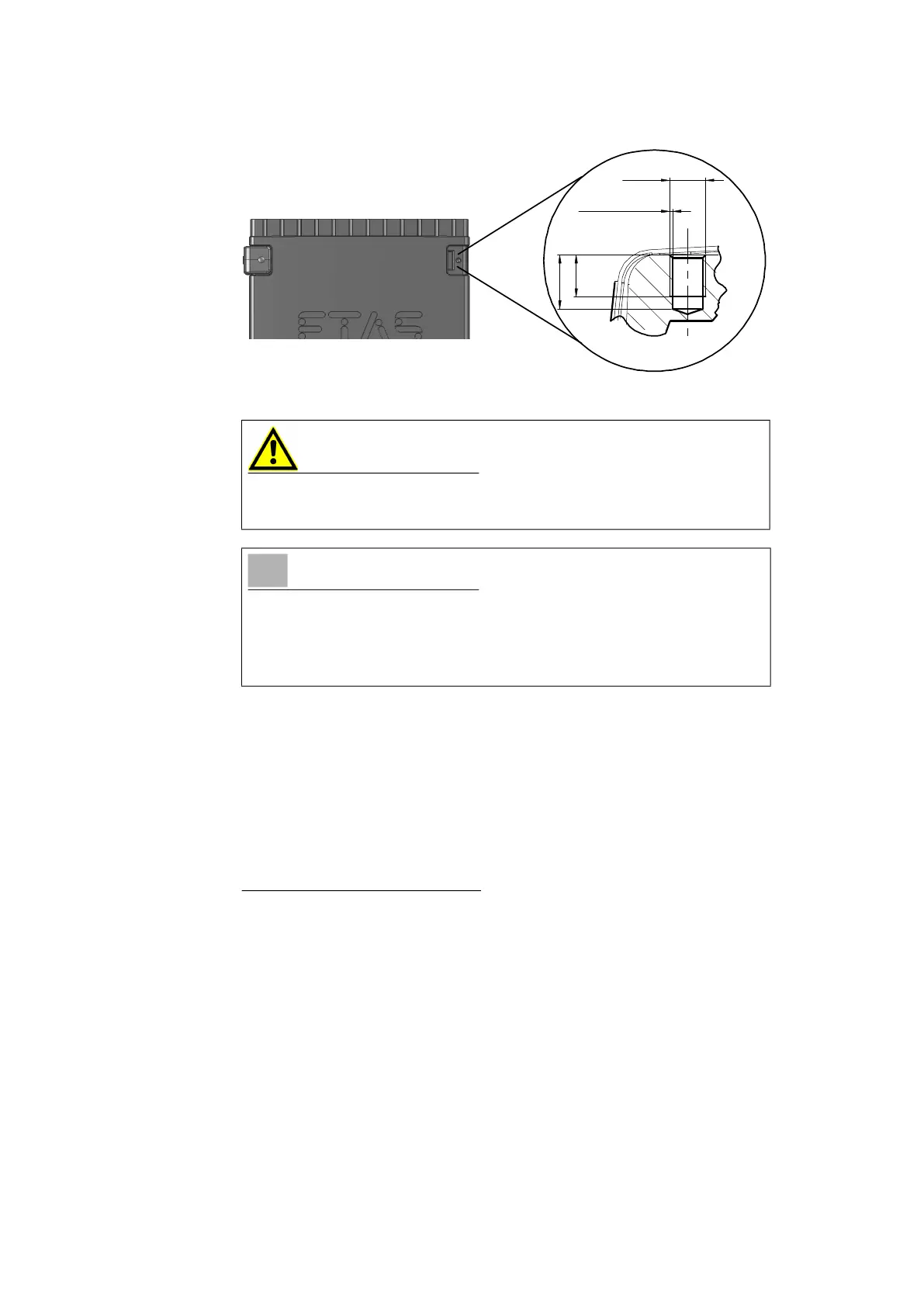
Fig. 6-2 Tapped blind hole
6.1.3 Connecting Several Modules Mechanically
As ETAS system housing was used, the ES592.1 can also be connected to
modules of the ETAS compact line (ES59x, ES6xx, ES910). These can be com
-
bined easily using the T-Brackets provided to form larger blocks.
You can attach a further module of the ETAS compact line under the ES592.1.
Just remove the four plastic feet on each of the relevant device sides and
attach the T-Brackets provided in their place.
To connect modules mechanically:
1. Remove the four plastic feet from the bottom of the ES592.1
so a further module can be attached.
This makes the assembly slits for the T Brackets accessible.
You can attach a further module under the ES592.1.
2. Remove the four plastic feet on the relevant side of the second
module.
3. Turn the seals of the T-Brackets so they are at a right angle to
the longitudinal axis of the brackets
4. Click two brackets into the assembly slits on one long side of
the first module.
5. Click the second module into the two T-Brackets.
CAUTION
The electronic can be damaged or destroyed!
Do not rework the threaded hole.
NOTE
Use excluding M3 cylinder screws and fastening the module onto your carrier
system with a max. torque of 0.8 Nm.
The max. length of engagement into the tapped blind hole of housing is 3 mm
(see
Fig. 6-2 on page 28).
M3
0.25 x 45°
3.5
min
4.5 max