ETAS Technical Data
ES592.1 - User Guide 50
8.10 Pin Assignment
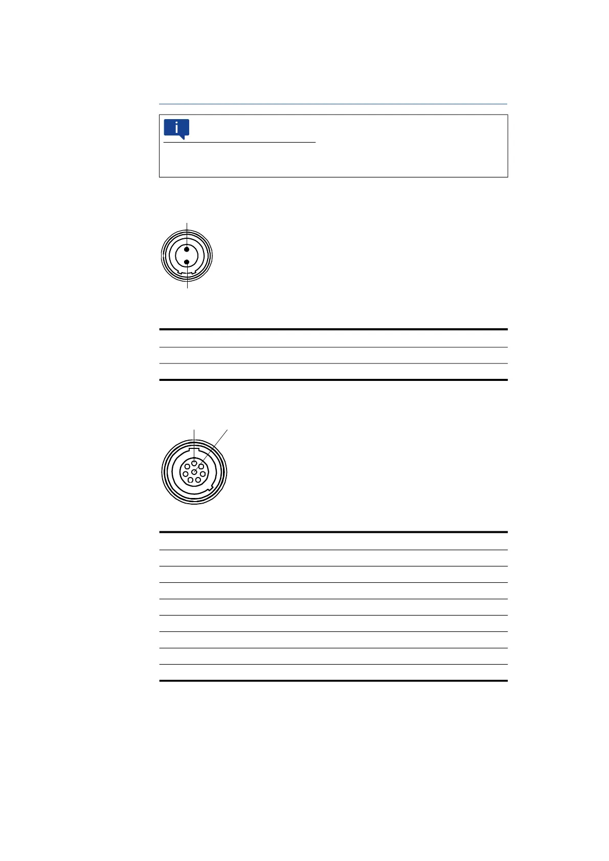
8.10.1 Power Supply Interface (7-29V)
Fig. 8-2 Power Supply Interface (7-29V)
8.10.2 Host Interface (HOST)
Fig. 8-3 Host Interface (HOST)
NOTE
All connectors are shown with a view of the interfaces of the ES592.1. All
shields are at case potential.
Pin Signal Meaning
1 UBATT+ Supply voltage, plus
2 Ground Ground
Pin Signal Meaning
1 - Reserved
2 - Reserved
3 - Reserved
4 RX+ Received data, plus
5 TX- Send data, minus
6 RX- Received data,, minus
7 - Reserved
8 TX+ Send data, plus


 To Next Page