S5 Control Surface/Frame Manual Page 16 Version 1.0 ©1999 Euphonix, Inc.
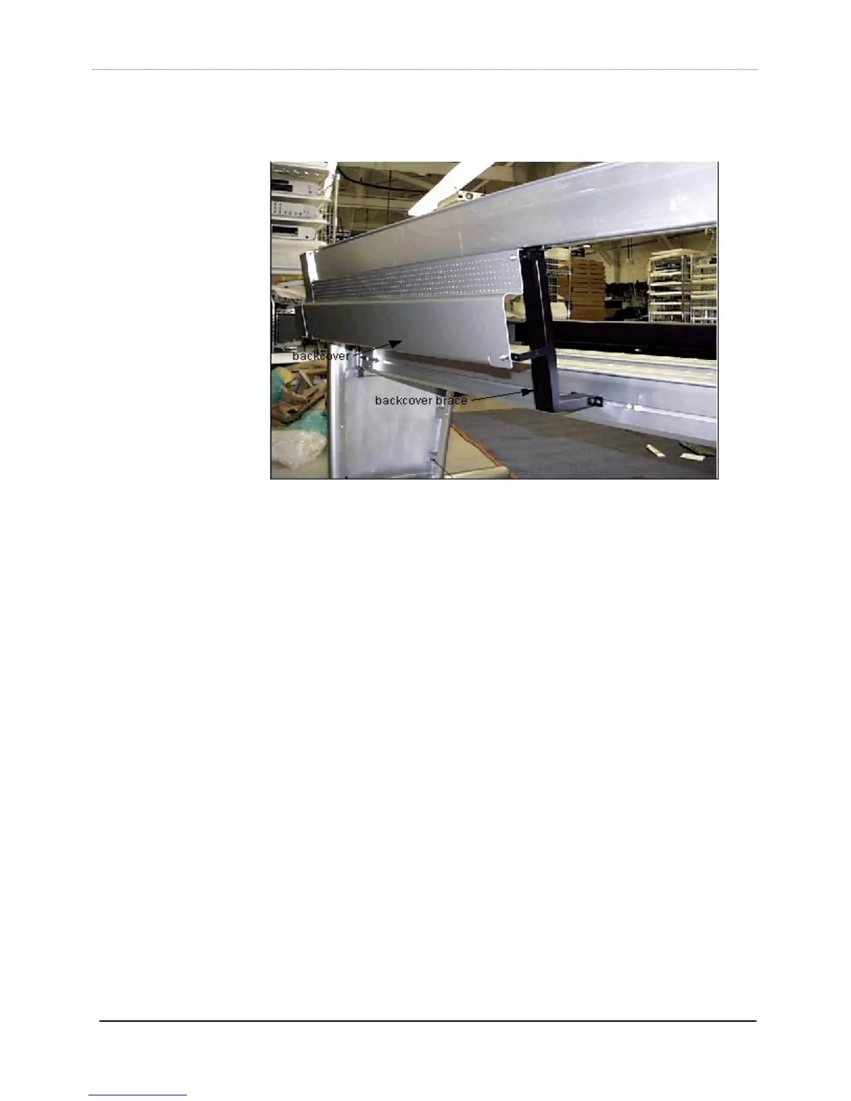
15) Using a 5/32“ hex driver and 1/4x20/3/8 button head screws (044-07236-00), install
the back covers on the braces.
16) Determine where the power strips (part#600-07223-00)) are going to be mounted on
the rear box beam, line up the slide nuts in the box beam to match the mounting
holes of the power strips, and use a ¼” hex driver with 5/16x18x0.375 socket head
screws to mount the power strips into the slide nuts.
17) Determine where the keyboard drawer (item 19, kbd drawer) is going to be located,
then line up the slide nuts in both box beams (the distance between the screw holes
on each box beam end of the keyboard drawer is xx”). Use a ¼” hex driver with
5/16x18x0.375 socket head screws to mount the drawer into the slide nuts.