S5 Control Surface/Frame Manual Page 26 Version 1.0 ©1999 Euphonix, Inc.
DB25 Electrical Specification:
The +5V output on the connector is protected internally by a 200mA self-resetting
fuse. If LED drive outputs are used, it is recommended that several +5V connections
be used to drive the anodes of the LED’s (at least one +5V wire per LED used). The
active-low LED drive outputs are current limited by internal 110 ohm series resistors,
and are capable of sinking 20mA each. The active-high switch inputs are TTL-level
inputs with 100K pull-down resistors.
Typical Usage:
Currently, the software supports remote talkback switching and status on Switch
inputs 1-4 and LED outputs 1-4 on the CM401 Expansion Port only. Functionality is
as follows:
Function Triggered by Status shown on
Talkback ! Mon A Switch 1 input
(momentary)
LED 1 output
Talkback ! Mon B Switch 2 input
(momentary)
LED 2 output
Talkback ! Mon C Switch 3 input
(momentary)
LED 3 output
Talkback ! Mon D Switch 4 input
(momentary)
LED 4 output
For example, while Switch 1 is pressed down, the Talkback mic signal will be
routed to the Mon A output, and LED 1 will light during the time that the switch is
pressed down. Also, if Talkback ! Mon A is activated from the console itself, LED 1
will also light, to indicate the status.
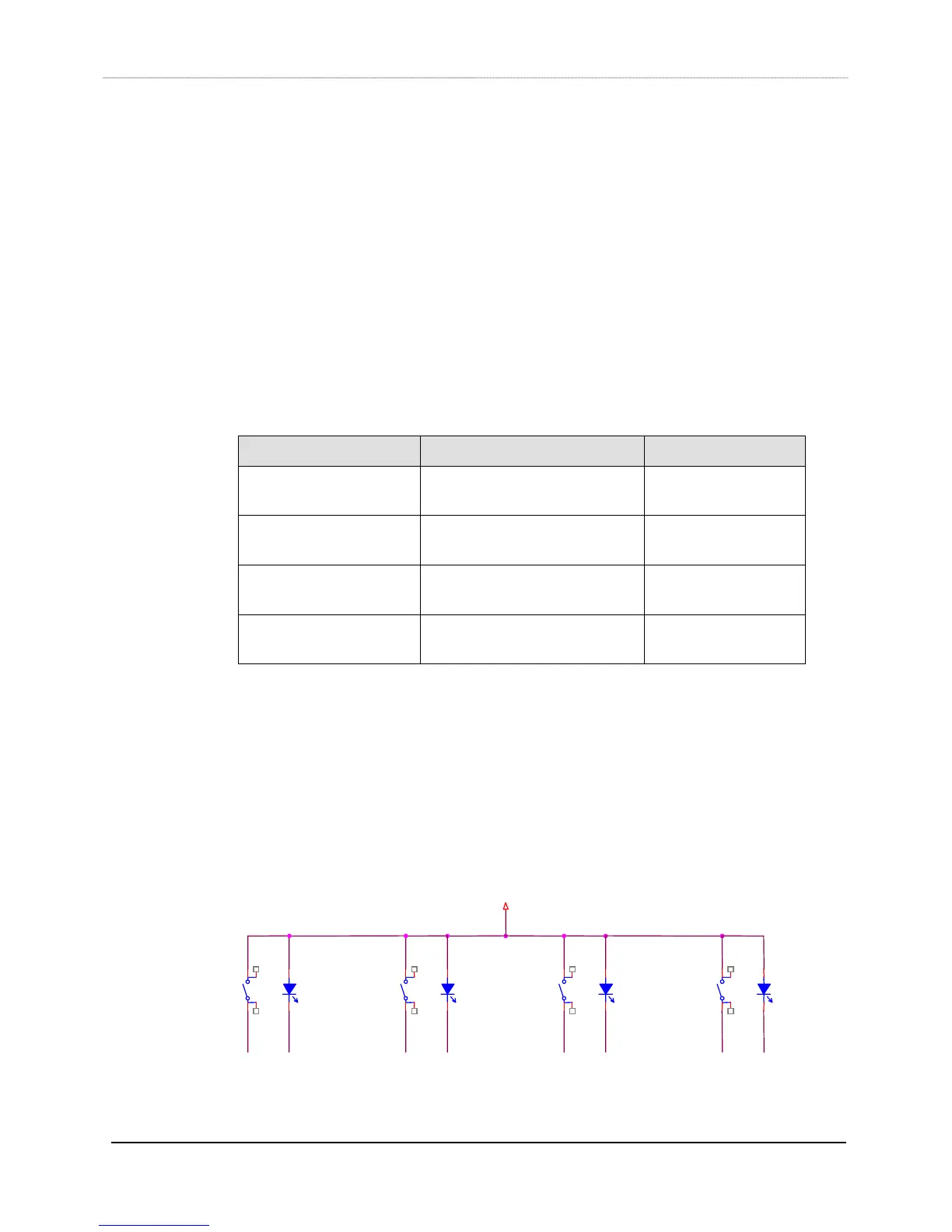
Pressing SW1A routes the Talkback signal to Mon A, and the SW1B LED lights to
indicate the Talkback!Mon A status.
+5V
SW1A
2
3
1
4
SW2A
2
3
1
4
SW3A
2
3
1
4
SW4A
2
3
1
4
SW1B
LIGHTED SW ITCH
6
5
SW2B
LIGHTED SW ITCH
6
5
SW3B
LIGHTED SW ITCH
6
5
SW4B
LIGHTED SW ITCH
6
5
PINS 3, 6, 9, 12, 13, 14, 17, 20, 23
PICK ANY 4
PIN 2
PIN 1
PIN 16
PIN 15
PIN 5
PIN 4
PIN 19
PIN 18