S5 Control Surface/Frame Manual Page 10 Version 1.0 ©1999 Euphonix, Inc.
User Reference - Frame
Assembling the S5 Frame
Tools required:
• Hex drivers, 1/8”, 3/16”, 7/32”, ¼”, 5/32”
• Flat-bladed screwdriver, ¼”
• Socket wrench, ½”
• Silicon grease for bolts (Finish Line bicycle grease works great)
• Aux leg (item 20, not shown on some frame drawings)
• Bus wire, two 24” pieces
• Tap set for 3/8” 24 (3/8” 16 for newer box beams) and 5/16 18 threads
Minimum number of people required: 2. For a 12-foot frame, 3 people are
required.
Refer to the System 5 Frame drawings (pages 7-8) and the Parts Lists at the end
of this manual to help with parts identification and visualization of the steps set
forth in this procedure.
1) Verify that all screws and bolts have been greased. If they aren’t greased, apply
silicon grease to all of them.
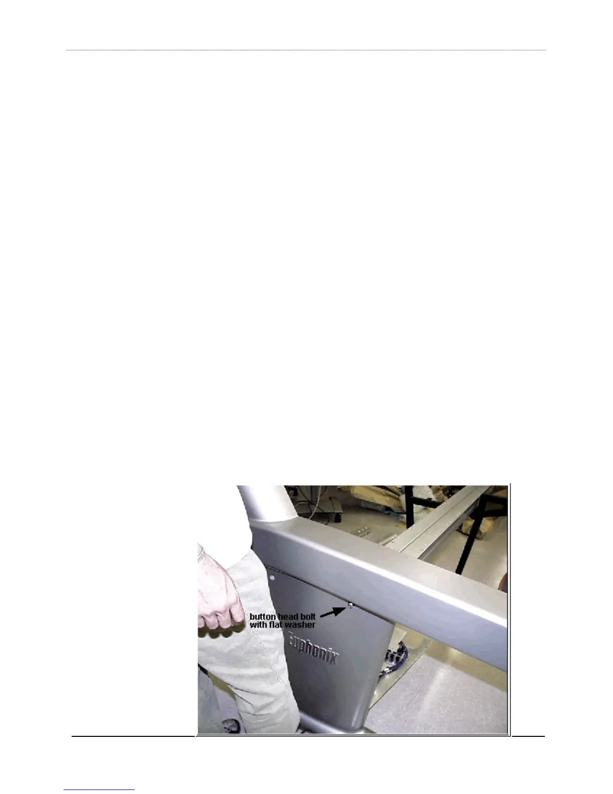
2) Start with inserting the middle box beam (item 2) in the left leg (item 3, Leg Left).
You may have to drop the leg panel (item 18, legpnl) to get it in easily. Two people
need to hold up the beam, while the third person holds up the leg. Guide the beam
into the leg (flat side up). Insert a 3/8” 24x1.5 button head bolt (046-06421-00)
with a 3/8” flat washer (081-07193-00) through the leg hole and into the beam,
being careful not to strip the threads. Tighten the bolt fully, using a 7/32” hex