S5 Control Surface/Frame Manual Page 11 Version 1.0 ©1999 Euphonix, Inc.
driver.
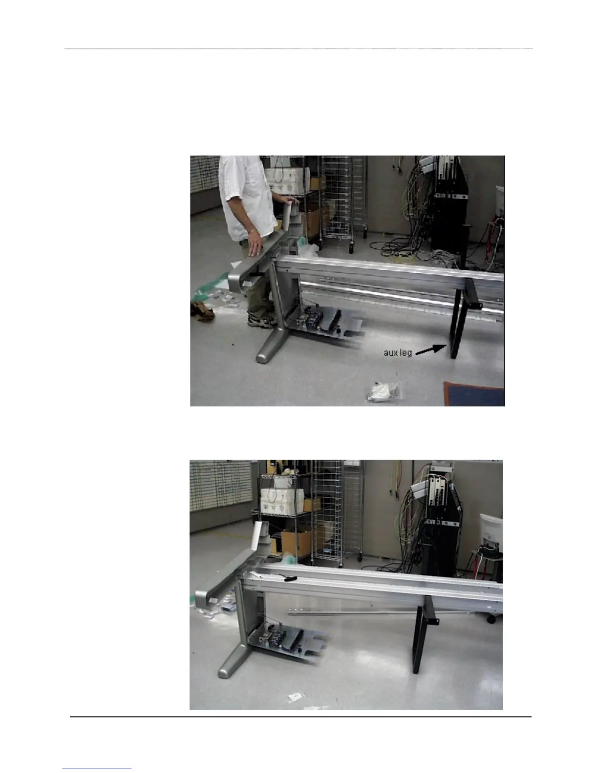
3) After the beam is attached to the leg, the auxiliary leg (12 ft frame only, item 20)
can be put underneath the beam near the center to hold it up. Secure the auxiliary
leg to the beam by inserting a “T” nut (000-06690-00) into the beam, and thread a
5/16x18x0.50 screw (044-07192-00) through the auxiliary leg mounting hole and
into the “T” nut.
4) Insert the rear box beam (item 2) into the left leg next, using the same techniques
outlined in step 2. The auxiliary leg can help to hold up the beam.