S5 Control Surface/Frame Manual Page 12 Version 1.0 ©1999 Euphonix, Inc.
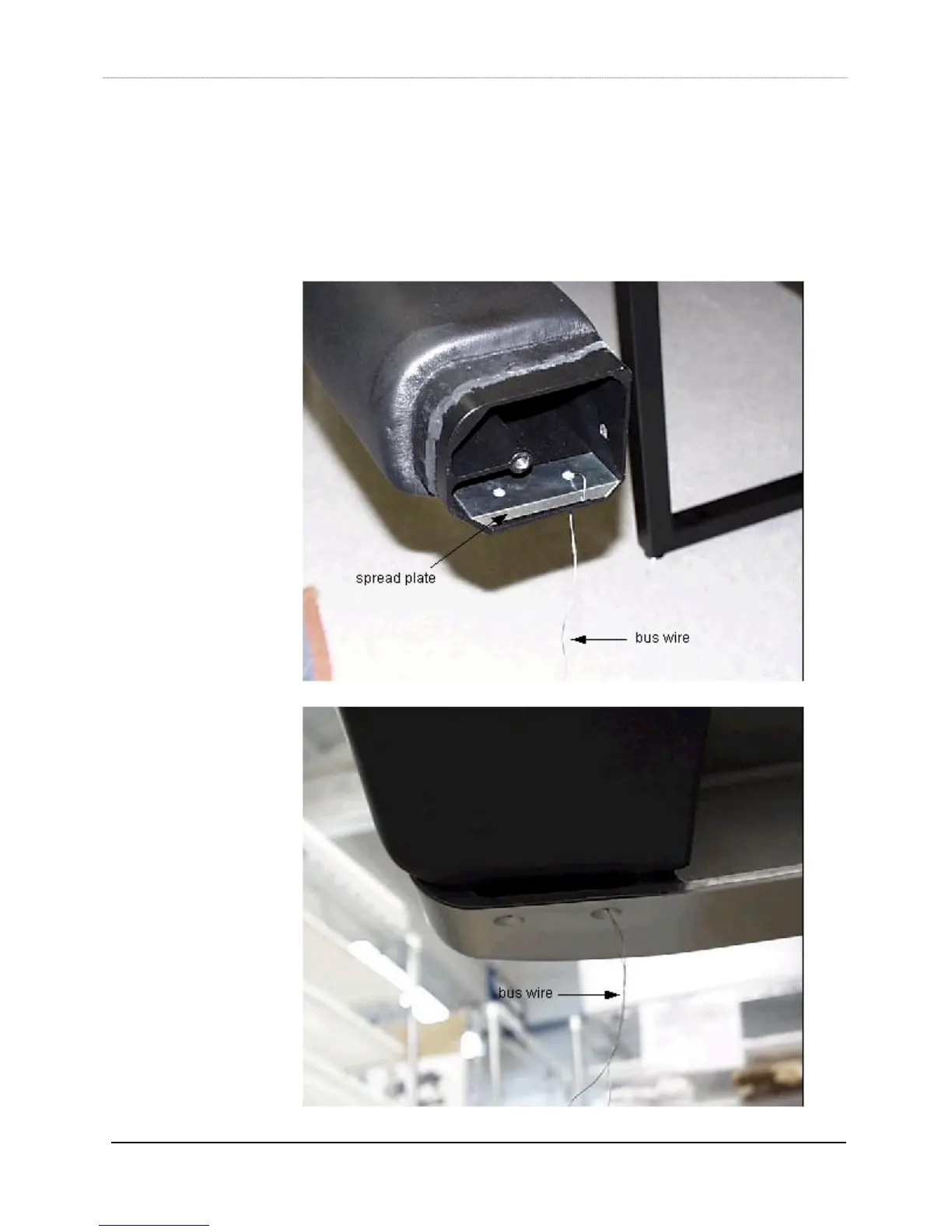
5) Prior to inserting the palm beam (item 7) into the left leg, thread the bus wire
through one of the holes of the spread plate (part#726-06404-01, item 8), twist-
locking the wire at the spread plate end. Run the other end of the wire through its
matching bolt hole on the left end of the palm beam. The spread plate should mount
inside the end of the palm beam, flat side up. As the palm beam is inserted into the
left leg (rounded side out) guide the bus wire into the matching bolt hole of the leg.
Insert a 3/8” 24x1.5 button head bolt through the leg hole and into the beam, using
the same techniques outlined in step 1. The auxiliary leg can help to hold up the