S5 Control Surface/Frame Manual Page 13 Version 1.0 ©1999 Euphonix, Inc.
beam.
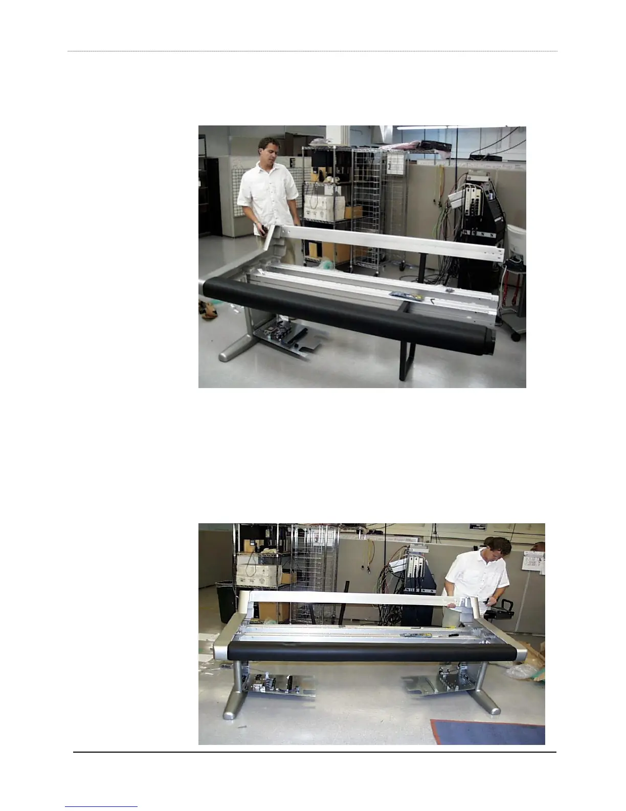
6) Insert the back beam (item 13) into the left leg, using the same techniques outlined
in step 1. The auxiliary leg can help to hold up the beam.
7) Insert as many “T” nuts in the beams as required. For example, you will need 3 “T”
nuts for the middle box beam’s inner channel and 3 “T” nuts for the palm beam’s
inner channel in order to install the keyboard tray. You will need 4 “T” nuts for each
back cover brace (item 15, brace 1), 2 for the back beam bottom channel and 2 for
the rear box beam outside channel. You will need 2 “T” nuts for each power strip,
usually mounted on the rear box beam.
8) With the auxiliary leg holding up one end of the S5 frame, insert the four beams into
the right leg (item 1, Leg Right), using the same techniques outlined in step 1.