S5 Control Surface/Frame Manual Page 14 Version 1.0 ©1999 Euphonix, Inc.
Also, for the palm beam, use the same technique with the spread plate and bus wire
as outlined in step 4.
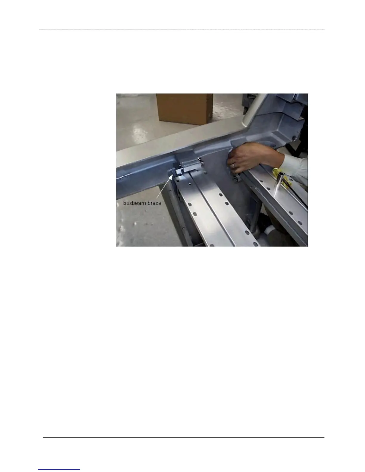
9) Install the four box beam braces (item 4) on each end of the box beams. Use four
5/16-18x3.5 bolts (043-06688-00) and four 5/16 lock washers (082-066889-00) for
each box beam brace. Use a ½” socket wrench. Do not tighten down fully until the
frame is fully loaded and its width is checked.
10) To secure the spread plates into the palm beam ends, pull down on the bus wire, and
line up the spread plate screw holes with the leg screw holes. With a 3/16” hex
driver, insert a 5/16-18x1.125 flathead screw (046-06409-00) into spread plate screw
hole sans the bus wire. Once the screw is threaded in and tightened down, remove
the bus wire and insert the other counter-sunk screw in the screw hole that the bus
wire previously occupied. You may have to loosen the other screw a little in order to
remove the bus wire.
11) Using the 3/16” hex driver and 5/16-18x2.25 flathead screws (046-06401-00), install
the spread plates (part# 726-06402-01, items 5 & 6) into the back beam ends. (Like
spread plate pictured in Step 5.)
12) Install all the modules into the frame to ensure that their surfaces are flush. Use the
thumbscrews (936-07240-01, S5 thumbscrew kit, 4 per module) to secure the
modules to the box beams. Before installing the 401 module permanently into the
frame, attach the talkback mic bracket (936-07219-01, S5 talkback mic kit) into the
middle top screw hole of the SBC panel, using the screw and insulating washer
supplied in the S5 talkback mic kit.
13) After verifying that the control surface is acceptable, tighten all loose screws and
bolts in the frame. Tighten the bolts on the box beam braces only until their lock
washers flatten, and no further. You will have to temporarily remove the modules on
each end of the frame to be able to tighten the box beam braces.