S5 Control Surface/Frame Manual Page 25 Version 1.0 ©1999 Euphonix, Inc.
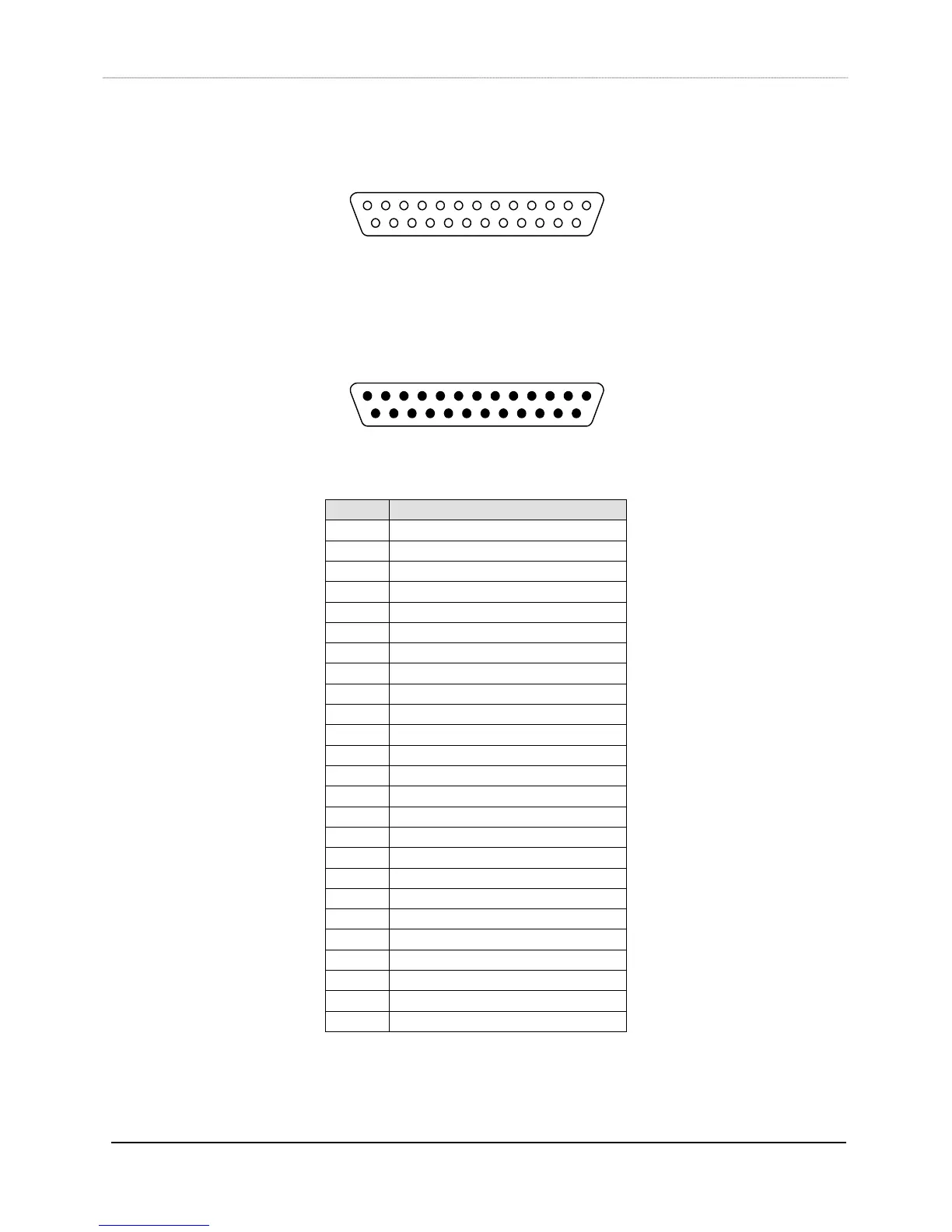
Looking into the FEMALE connector on the module:
Looking into a MALE cable connector:
Pin # Signal
1 LED 1 output (active low)
2 Switch 1 input (active high)
3 +5V
4 LED 3 output (active low)
5 Switch 3 input (active high)
6 +5V
7 LED 5 output (active low)
8 Switch 5 input (active high)
9 +5V
10 LED 7 output (active low)
11 Switch 7 input (active high)
12 +5V
13 +5V
14 +5V
15 LED 2 output (active low)
16 Switch 2 input (active high)
17 +5V
18 LED 4 output (active low)
19 Switch 4 input (active high)
20 +5V
21 LED 6 output (active low)
22 Switch 6 input (active high)
23 +5V
24 LED 8 output (active low)
25 Switch 8 input (active high)
13
1
14
25
1 13
14 25