ISIS user manual
Issue G
136
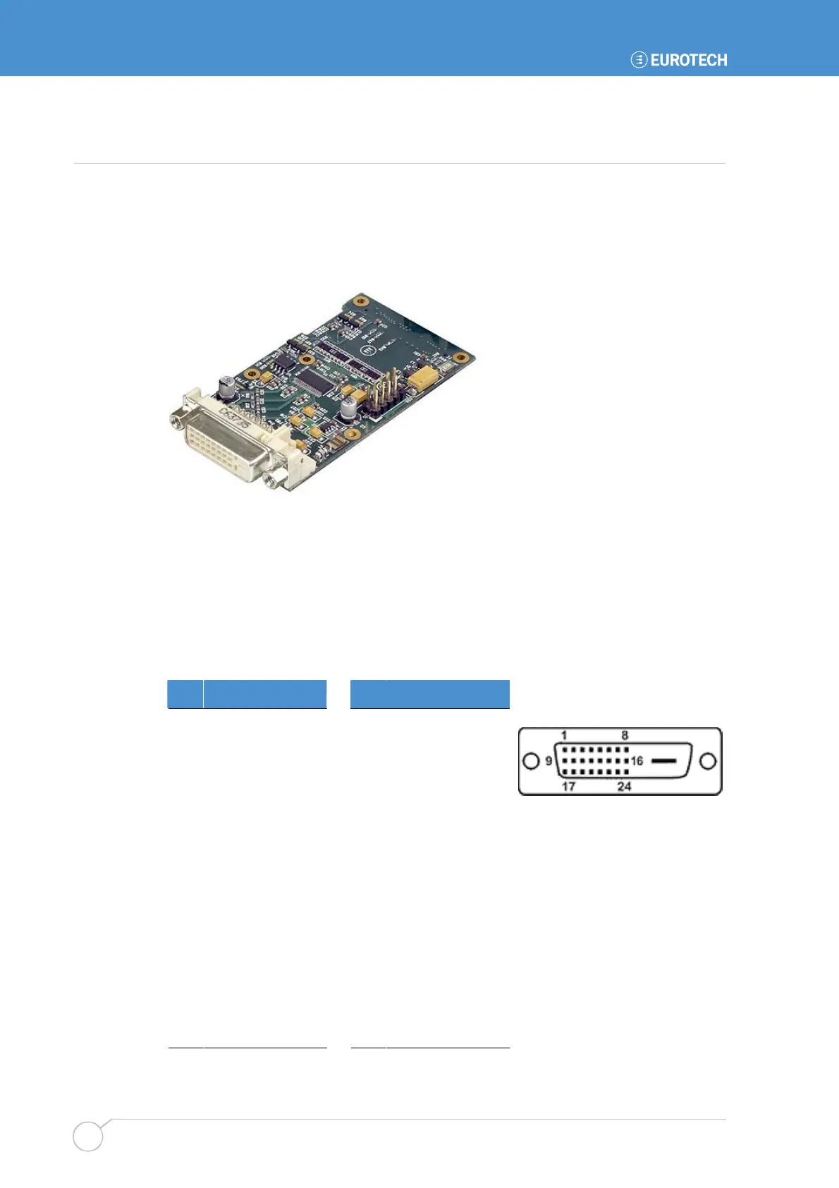
Appendix E – DVI video option board
The DVI video option board provides the ability to connect single channel DVI 1.0
compliant display devices to the APOLLO board. This can be used in conjunction with the
LVDS or VGA display interfaces to provide dual display capabilities. The following
connections refer to pinouts on the DVI board. The option board also provides the same
USB functionality as the USB 5/6 breakout and is mounted in the same location.
BIOS setup
To enable the operation of the DVI video option board the BIOS setup option IGD – Boot
Type in the Advanced Video (Intel IGD) Control Sub-Menu should be set to the
External Flat Panel (EFP) option.
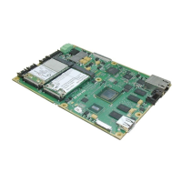
J2 – DVI connector
DVI-D (Digital Visual Interface – Digital only)
Pin Signal name Pin Signal name
1 TMDS D2– 13 No connect
2 TMDS D2+ 14 +5V Power
3 TMDS D2 shield 15 Ground
4 No connect 16 Hot plug detect
5 No connect 17 TMDS D0–
6 DDC clock 18 TMDS D0+
7 DDC data 19 TMDS D0 shield
8 No connect 20 No connect
9 TMDS D1– 21 No connect
10 TMDS D1+ 22 TMDS clock shield
11 TMDS D1 shield 23 TMDS clock+
12 No connect 24 TMDS clock–