Model 5600ACO2 Automatic Changeover Unit
ACO GPI1 ACO GPI2 GND GND ACO GPO1 ACO GPO2
MSC A GPO1 MSC A GPO2 MSC B GPO1 MSC B GPO2
MSC A & B
GPI1
MSC A & B
GPI2
Table 2-3: ACO CTRL/STATUS and MSC GPIO Terminal Strip Pin Definitions
2.1.4. Ethernet Connections
The 5600ACO2 can be configured using the VistaLINK
®
-C Configuration tool connected by Ethernet.
(See section 5.1.1 for information on configuring the IP address of the 5600ACO2 and section 5.1.2 for
information about installing and using the VistaLINK
®
software)
The 5600ACO2 is designed to be used with either 10Base-T (10 Mbps) or 100Base-TX (100 Mbps)
also known as Fast Ethernet, twisted pair Ethernet cabling systems. When connecting for 10Base-T
systems, category 3, 4, or 5 UTP cable as well as EIA/TIA – 568 100Ω STP cable may be used. When
connecting for 100Base-TX systems, category 5 UTP cable is required. The cable must be “straight
through” with a RJ-45 connector at each end. Make the network connection by plugging one end of the
cable into the RJ-45 receptacle of the 5600ACO2 and the other end into a port of the supporting hub.
The straight-through RJ-45 cable can be purchased or can be constructed using the pinout information
in Table 2-4. A colour code wiring table is provided in Table 2-4 for the current RJ 45 standards (AT&T
258A or EIA/TIA 258B colour coding shown). Also refer to the notes following the table for additional
wiring guide information.
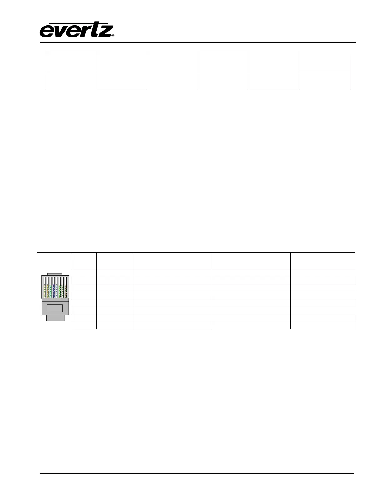
Pin # Signal EIA/TIA 568A AT&T 258A or
EIA/TIA 568B
10BaseT
or 100BaseT
1 Transmit + White/Green White/Orange X
2 Transmit – Green/White or White Orange/White or Orange X
3 Receive + White/Orange White/Green X
4 N/A Blue/White or Blue Blue/White or Blue Not used (required)
5 N/A White/Blue White/Blue Not used (required)
6 Receive – Orange/White or Orange Green/White or Green X
7 N/A White/Brown White/Brown Not used (required)
Pin
1
8 N/A Brown/White or Brown Brown/White or Brown Not used (required)
Table 2-4. Standard RJ45 Wiring Colour Codes
Note the following cabling information for this wiring guide:
•
•
•
•
•
Only two pairs of wires are used in the 8-pin RJ 45 connector to carry Ethernet signals.
Even though pins 4, 5, 7 and 8 are not used, it is mandatory that they be present in the cable.
10BaseT and 100BaseT use the same pins, a crossover cable made for one will also work with the
other.
Pairs may be solid colours and not have a stripe.
Category 5 cable must use Category 5 rated connectors.
The maximum cable run between the 5600ACO2 and the supporting hub is 300 ft (90 m). The
maximum combined cable run between any two end points (i.e. 5600ACO2 and PC/laptop via network
hub) is 675 feet (205 m). When you have connected the 54600ACO2 and set up the IP address you
should ‘ping’ the device from your PC to make sure that it is connected correctly.
INSTALLATION
Revision 1.3 Page 2-3