OILING SYSTEM
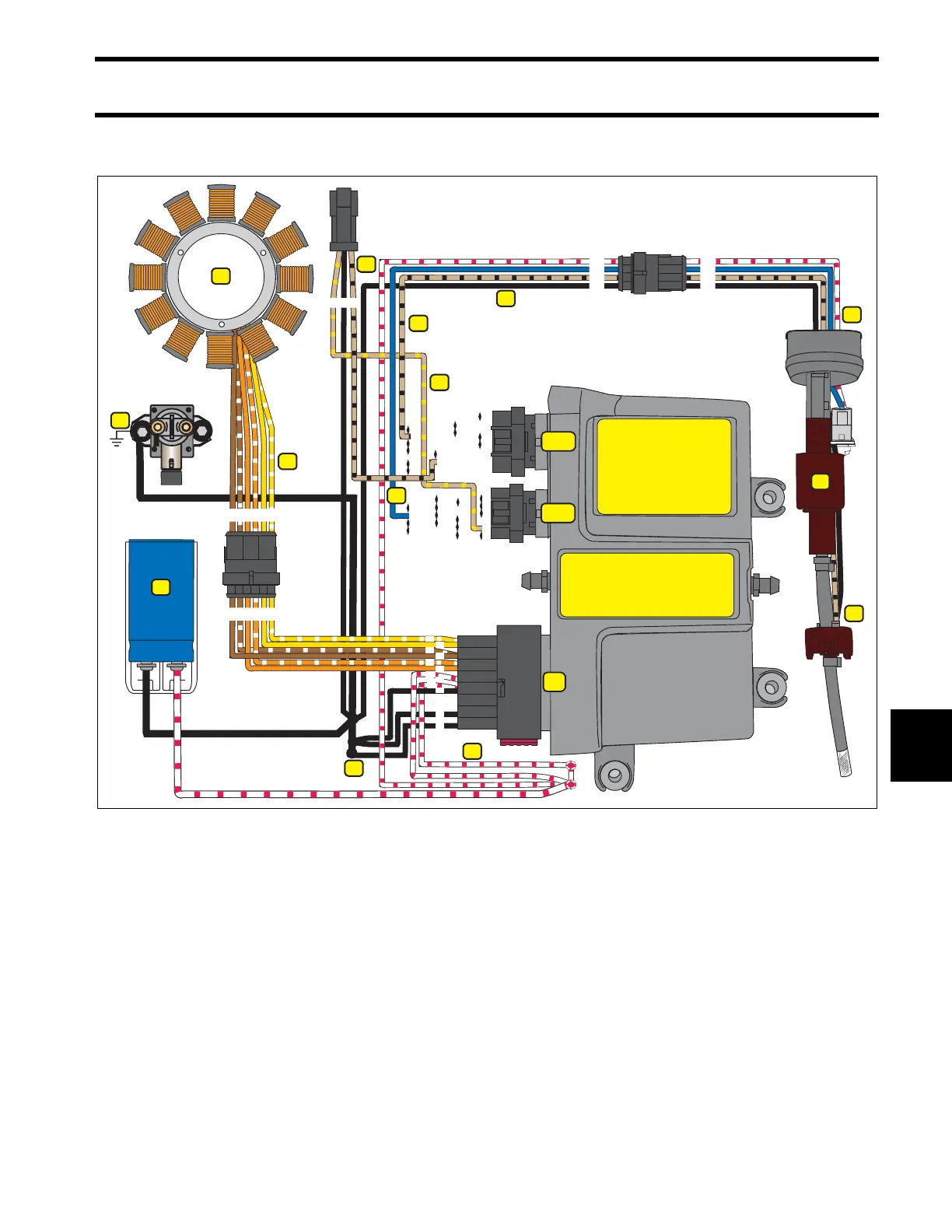
OILING SYSTEM CIRCUIT DIAGRAM
179
9
OILING SYSTEM CIRCUIT DIAGRAM
1.
2.
3.
4.
5.
6.
7.
8.
9.
10.
11.
12.
13.
14.
Stator
Stator output (55 V)
Alternator grounds (BLACK)
Oil Injector ground (BLACK)
Alternator output, WHITE / RED wires (55 V)
Capacitor (55 V)
Main harness ground (BLACK)
55 V to injection pump (WHITE / RED)
EMM injector control (BLUE)
Oil injection pump
Low oil switch
Low oil switch to EMM (TAN/BLACK)
Low oil signal to SystemCheck gauge (TAN/BLACK)
No oil signal to SystemCheck gauge (TAN/YELLOW)
1
2
3
5
6
7
8
12
13
14
15
16
9
10
11
13
12
11
10
9
8
7
6
5
4
3
2
1
8
9
18
17
16
15
14
13
12
11
10
13
12
11
10
17
16
15
14
34
33
32
31
30
29
28
27
26
24
25
23
22
21
20
19
18
26
24
25
23
22
21
20
19
17
16
15
14
18
J1-B
J1-A
J2
4
1
23456
234561
2
3
4
1
2
3
4
1
345
006480
7
6
4
3
2
1
5
2
1
3
7
6
11
4
5
8
9
10
12
13
14