34
INSTALLATION AND PREDELIVERY
BOAT RIGGING
Cable and Hose Installation
Before installation, identify all required wiring,
cables, and hoses:
• Throttle and shift cables
• Instrument harnesses
• Battery cables and switches
• Oil tank sender harness
• Fuel supply hose
• Primer bulb or primer pump
• Oil supply hose
Determine whether any additional wiring or hoses
will be needed for accessory gauges or batteries:
• Speedometer pick-up hose
• Mechanical water pressure gauge hose
• Accessory battery charging kit
• CANbus adapter harnesses
• CANbus water pressure sensor kit
• CANbus oil level sensor kit
Cable and Wire Harness Routing
Remote control cables, wiring, and hoses must
follow a similar path into the lower motor covers.
Select the best routing for the specific application.
All cables, wiring, and hoses must be long enough
to provide adequate slack. Check clearances at all
possible combinations of trim angles and steering
positions.
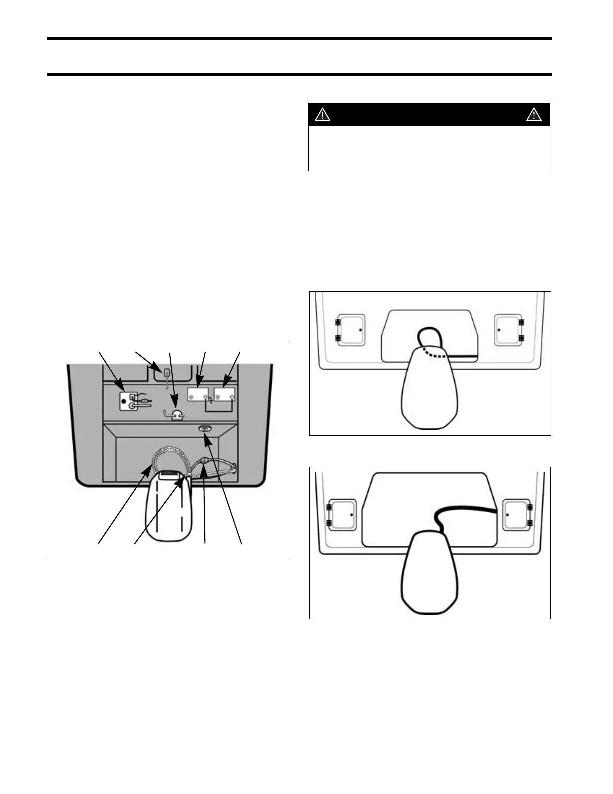
Typical outboard installation
1. Oil tank
2. Anti-siphon valve
3. Water separating fuel filter
4. Starting battery
5. Accessory battery
6. Flexweave protective sleeve
7. Access cover
8. Primer bulb
9. Battery switch
DRC6487
12345
6 7 8 9
WARNING
Improper installation and routing of out-
board controls could wear, bind, and dam-
age components, causing loss of control.
Typical Small Splash Well DRC7799
Typical Large Splash Well DRC7797