34000 Autry Street, Livonia, MI 48150 • 800.968.5530 • Fax 734.419.0209 • www.hamiltonengineering.com • LIT91127 REV 3/09
VENTING
Page 17 of 50
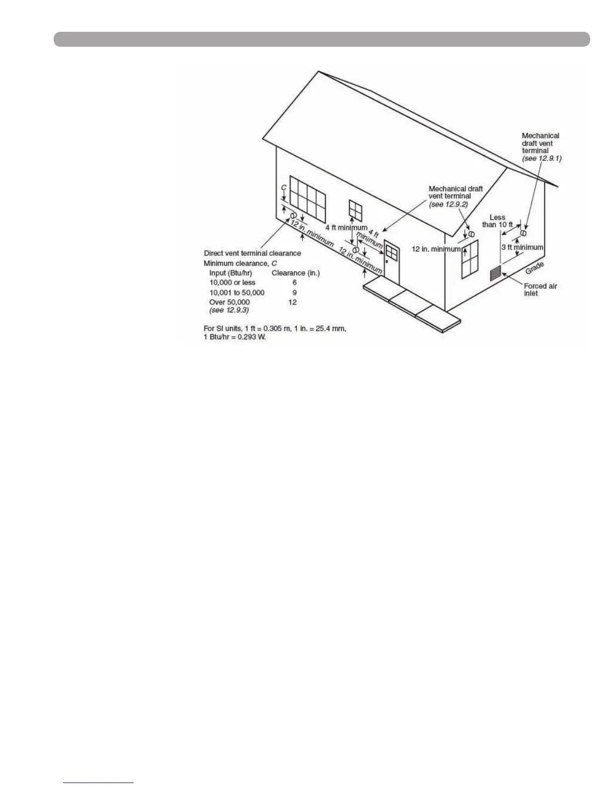
(FIGURE 4-1) EXIT TERMINALS OF MECHANICAL DRAFT AND DIRECT-VENT VENTING SYSTEM
* REFERENCE: THE NATIONAL FUEL GAS CODE 2009 EDITION
*IMPORTANT NOTE
HAMILTON ENGINEERING, INC.
RECOMMENDS A MINIMUM
CLEARANCE OF 4 FEET WHERE
THE EXHAUST PLUME CAUSED BY
THE UNIT MAY OBSTRUCT VIEWS
OR AFFECT THE COSMETIC LOOK
OF THE BUILDING. IN CANADA,
THERE IS A MINIMUM CLEARANCE
OF 10 FEET.
Through-the-Wall Vent Termination
12.9.1 A mechanical draft venting system shall terminate at least 3 ft (0.9 m) above any forced air inlet located
within 10 ft (3 m).
Exception No. 1: This provision shall not apply to the combustion air intake of a direct vent appliance.
Exception No. 2: This provision shall not apply to the separation of the integral outdoor air inlet and ue gas
discharge of listed outdoor appliances.
12.9.2 A mechanical draft venting system of other than direct vent type shall terminate at least 4 ft (1.2 m)
below, 4 ft (1.2 m) horizontally from, or 1 ft (300 mm) above any door, operable window, or gravity air inlet into
any building. The bottom of the vent terminal shall be located at least 12 in. (300 mm) above nished ground
level.
12.9.3 The vent terminal of a direct vent appliance with an input of 10,000 Btu/hr (3 kW) or less shall be located
at least 6 in. (150 mm) from any air opening into a building, an appliance with an input over 10,000 Btu/hr (3 kW)
but not over 50,000 Btu/hr (14.7 kW) shall be installed with a 9 in. (230 mm) vent termination clearance, and
an appliance with an input over 50,000 Btu/hr (14.7 kW) shall have at least a 12 in. (300 mm) vent termination
clearance. The bottom of the vent terminal and the air intake shall be located at least 12 in. (300 mm) above
nished ground level.