34000 Autry Street, Livonia, MI 48150 • 800.968.5530 • Fax 734.419.0209 • www.hamiltonengineering.com • LIT91127 REV 3/09
VENTING
Page 18 of 50
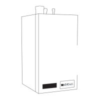
All horizontal runs must
be supported every 24"
Exterior wall
Intake
EVO
Exhaust
18" Minimum
24" Maximum
24" or 12" above
maximum snow level
whichever is greater
Right Side View
1/4" ft. slope to appliance
DIAGRAMS FOR SIDEWALL VENTING
8
Front Elevation
8"
18" Minimum
- OR -
VENTING FOR MULTIPLE
UNITS, with vents all on same
horizontal plane, spaced at least
8 inches apart, and at level of
highest unit.
PLEASE NOTE:
Exhaust must not terminate
beneath an overhang!
(FIGURE 4-2) SIDEWALL VENT WITH DOWN ELBOW (INTAKE) & UP ELBOW (EXHAUST)
**IMPORTANT NOTE: All vent pipes must be glued, properly supported and the exhaust must be pitched a
minimum of a 1/4” per foot back to the heater (to allow drainage of condensate). All stainless venting must be
sealed at each joint per manufacturer’s instructions.
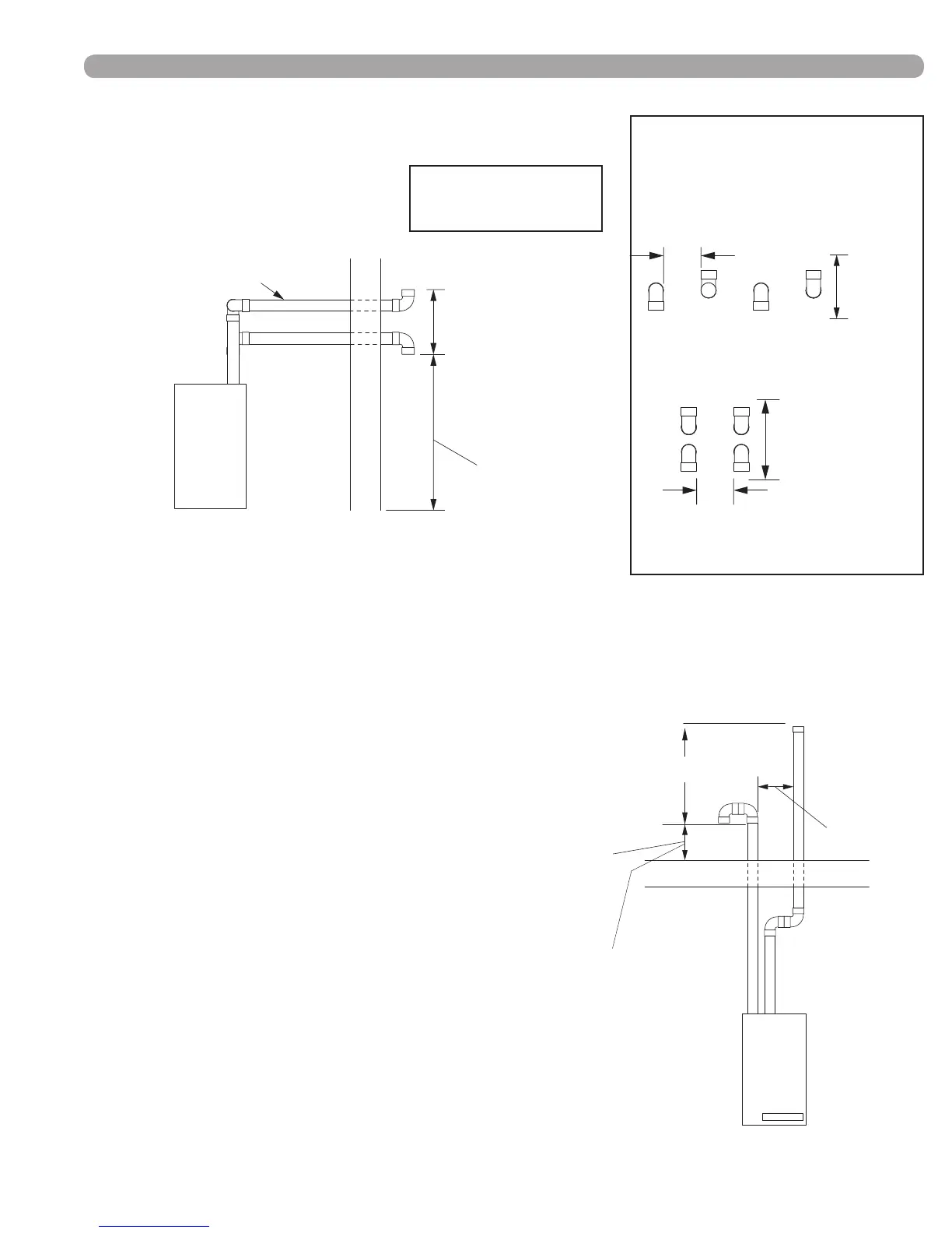
DIAGRAMS FOR VERTICAL VENTING
Roof
24" or 12" above
maximum snow level,
whichever is greater
Front View
Exhaust
Intake
EVO
8" minimum
Minimum 12" above
anything within 10 feet.
18" minimum
24"
maximum
(FIGURE 4-3) VERTICAL VENT WITH DOUBLE
ELBOW (INTAKE) & COUPLING (EXHAUST)
**IMPORTANT NOTE: All vent pipes must be glued,
properly supported and the exhaust must be pitched a
minimum of a 1/4” per foot back to the heater (to allow drainage
of condensate). All stainless venting must be sealed at each
joint per manufacturer’s instructions.
Front Elevation
(
Multiple Vents
)
8"
18" Minimum
24" Maximum
min.
min.