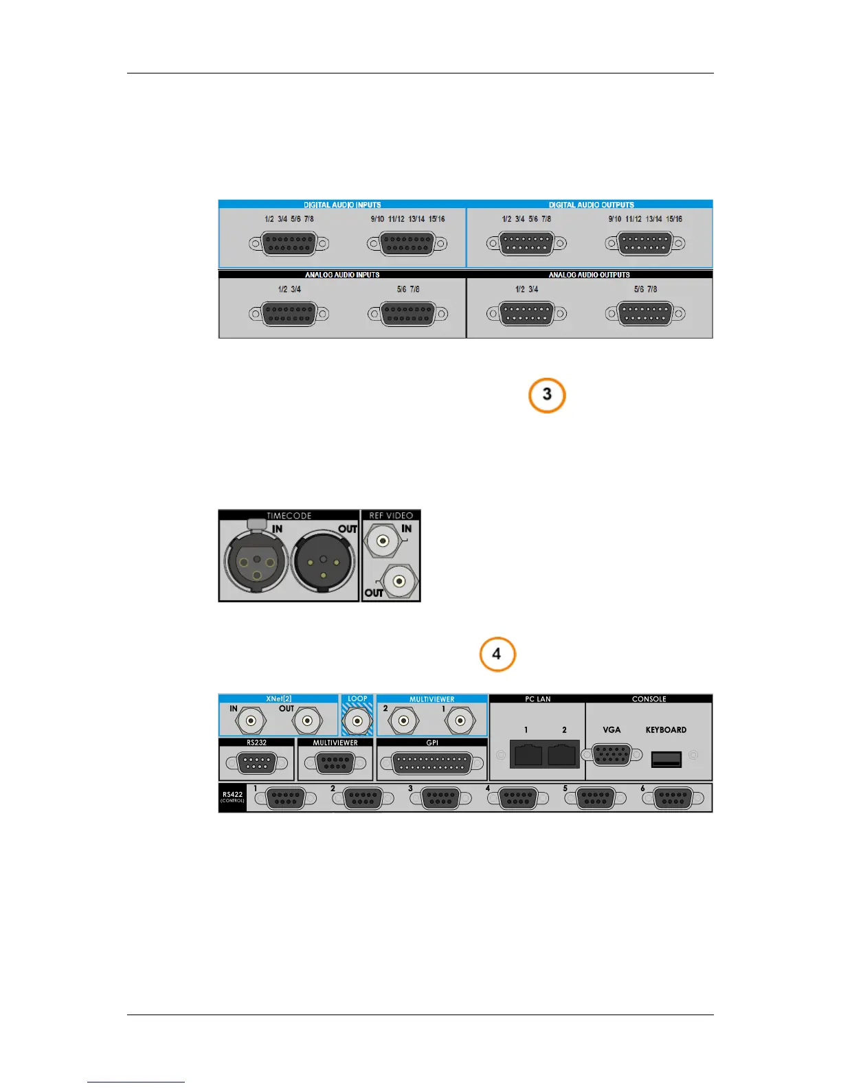
Digital and Analog DA-15 Connectors
• Digital audio: 4 multi-pin DA-15 connectors (2in and 2out)
• Analog audio: 4 multi-pin DA-15 connectors (2in and 2out)
Timecode and Video Ref Connectors
The Timecode connectors allow the server to receive the LTC timecode reference signal
and send the LTC timecode that corresponds to PGM1.
The Ref Video connectors allow the server to receive or send back the analog genlock
reference signal.
Controls and Communications
This rear panel part, located below the audio connectors, presents connectors that allow
the EVS server to communicated with other devices. The connectors are described from
top left to bottom right:
The XNet2 connectors allow the interconnection of EVS servers, and/or XStore in an
XNet2 network. The IN connector of a server is connected to the OUT connector of
another server, and so on to form a closed loop network.
The Loop connector allows the loop of PGM1 on REC1 to be able to use the internal loop
feature.
50 5. Hardware Installation and Cabling
EVS Broadcast Equipment SA Issue 12.05.C- November 2014


![Preview: EVS XT[2]](https://data.easymanua.ls/products/617905/200x200/evs-xt-2.webp)


