© Boule Medical AB, March 2018. Article no. 1504496 Page 7
1. Introduction
Analyzer Overview
5
67
1
3
4
2
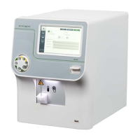
Figure 2: Analyzer cable and interface connections
Part Description/Function
1 USB host ports Connects analyzer to USB devices.
2 USB device port Connects analyzer to USB host.
3 Electronic sensors Connects Reagent level sensors to analyzer.
4 Power supply port Connects Main power outlet to analyzer.
5 Power switch Switches power On and O.
6 LAN port Connects analyzer directly to a computer.
7 Waste tube connection Connects Waste tube to analyzer.
8 Reagent tube connections Connects Lyse (yellow), Cleaner (blue), EOS regent (green) and Diluent
(red) to analyzer
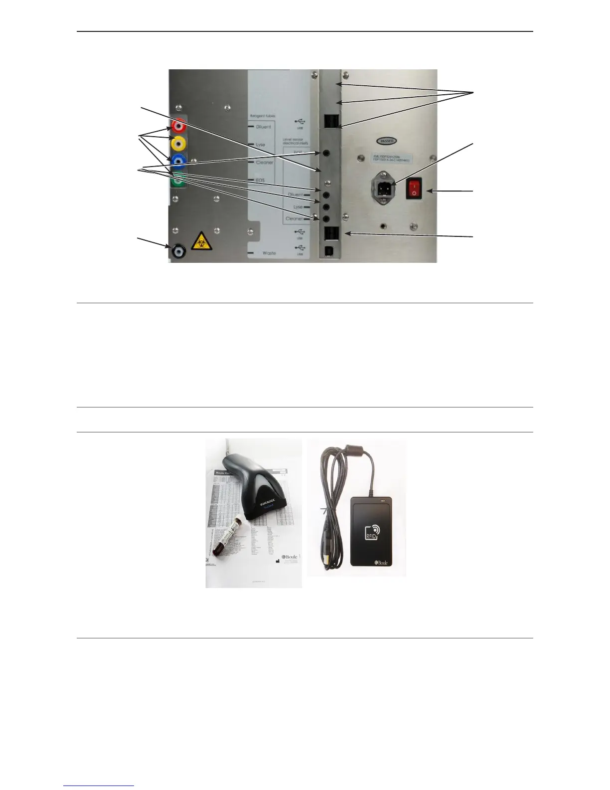
Figure 3: Barcode reader/RFID reader
Part Description/Function
1 Barcode Reader Enables operator to quickly enter patient, sample and control identications.
2 RFID Reader Enables operator to quickly enter reagent RFID tags
8