FX15 Controller Technical Bulletin
33
Connecting Passive Resistive Sensors
The FX15 analog inputs accept linear resistive signals as the Resistive
2kΩ. The Analog Input software can also linearize signals provided by
the most common sensors as Ni1000, A99, Pt1000, and NTC 2k2.
The inputs must be preconfigured in order to accept A99 resistive
signals by the application software resident in the FX15. The AI
Jumpers must be opened in order to accept resistance input (Factory
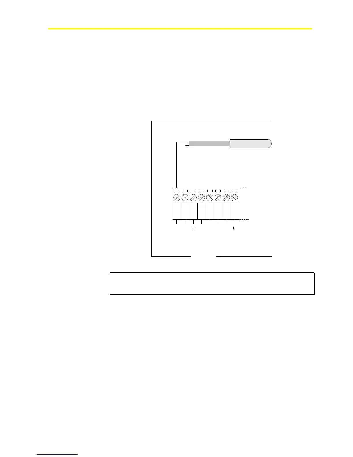
default setting). Figure 33 shows an A99 wiring diagram. The resistive
sensors have to be connected in the same way.
1 2 3
AGND
AI1
EXT V
4 5
AGND
AI2
6 7
AGND
AI3
8
EXT V
FX16
A99BB
Resistive Temperature Sensor
Figure 33: A99 Resistive Sensor Connection Diagram
IMPORTANT: The two resistive probe leads are the same, in that they have
no polarity; therefore, it is not necessary to respect any specific order when
connecting to the terminal block.
FX15