88 89
EN EN
889 5550
4. Start the engine of the generator.
When charging the battery, follow the instructions
of the car battery's manufacturer.
Do not start the engine of the motor vehicle and
electrical devices inside the vehicle during the
recharging process.
In the event that these instructions are not followed,
the generator and car battery may be damaged.
• ATTENTION
y The generators do not have car battery over-
-charging protection and, therefore, regularly
check the voltage on the car battery terminals
using avoltmeter, with the charging cables dis-
connected. The terminal voltage on the car bat-
tery should not be greater than 14.4 V (after dis-
connecting the charging cables; the charge level
relative to the voltage is listed in table 2). The
12V DC output from he generator is not intended
for charging any other batteries than 12V lead
car batteries.
• ATTENTION
y Hydrogen is produced during the car battery rechar-
ging process, which together with air creates an
explosive mixture. Therefore, do not smoke during
the recharging process and prevent access to any
flame or radiant heat sources. Ensure sufficient venti-
lation during the charging process.
y A car battery contains asulphuric acid solution,
which is astrong caustic agent, which causes chemi-
cal burns and tissue damage. When handling acar
battery, use suitable protective equipment, as amini-
mum rubber gloves and safety glasses. Never eat or
drink while handling the car battery.
y In the event that skin comes into contact with
electrolyte, immediately wash it under running water
and then wash with soap. In the event that this acid
solution is ingested, drink 200ml of clean unflavou-
red still water and immediately contact amedical
doctor or the Toxicological information centre.
In the event of ashort circuit, e.g. accidental con-
nection of the alligator clips +/- of the charging
cable or overloading by drawing agreater current,
the direct current circuit breaker will be triggered
(fig. 1, position 7). To restore current supply, first
eliminate the cause of the short circuit or overloa-
ding and then press the circuit breaker button (fig.
1, position 7).
5. Turn off the generator before disconnecting the char-
ging cables of the generator from the car battery.
6. First disconnect the alligator clip of the charging
cable from the grounded pole of the car battery
and then the alligator clip of the ungrounded pole
of the car battery.
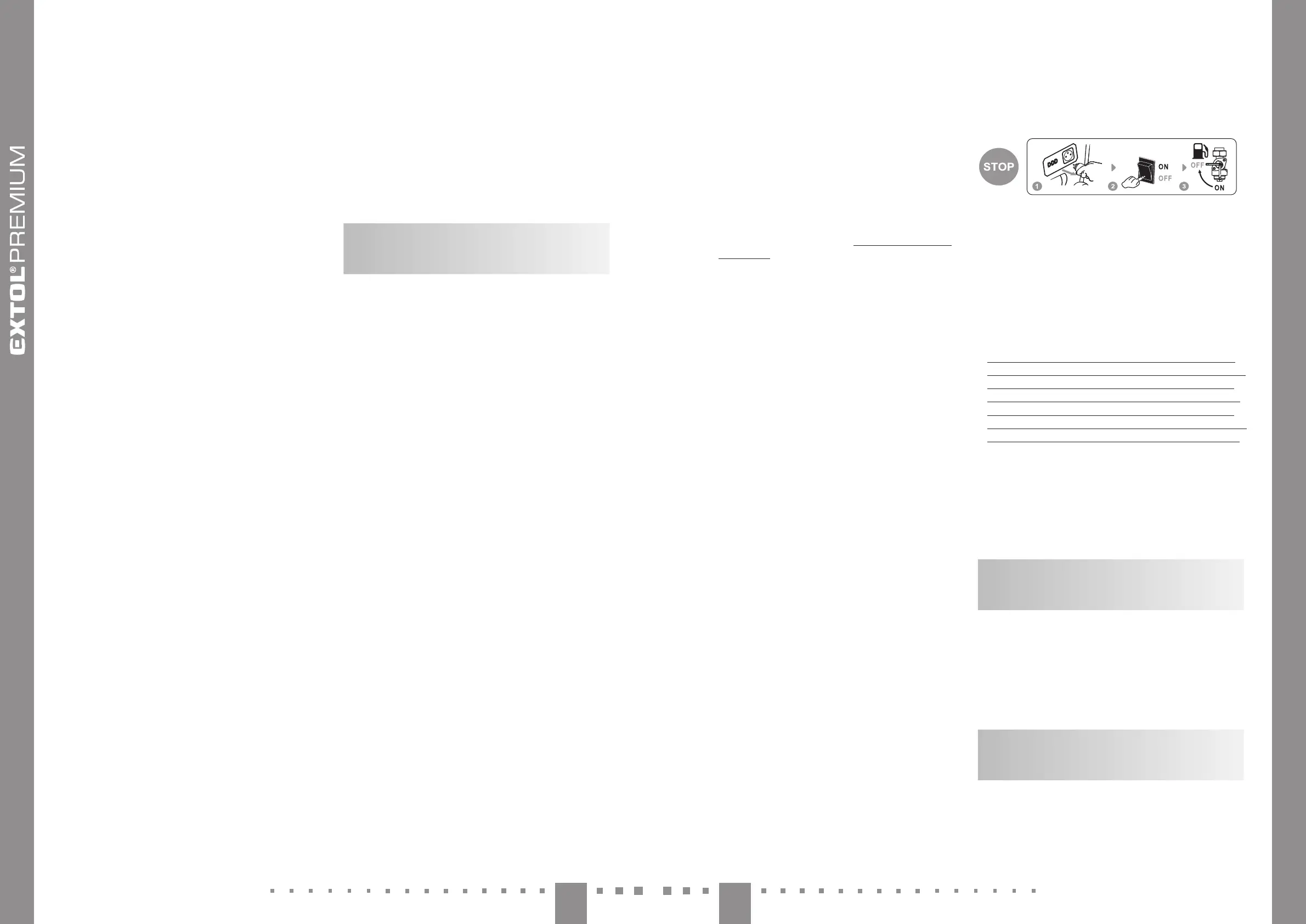
VII. Turning o
the generator -putting
out of operation
1. Disconnect the power cord plug from the socket of
the generator.
2. Set the power switch to the "OFF" position.
3. Shut off the fuel supply using the fuel valve by set-
ting the lever to position "OFF" on the pictogram.
If it is necessary to quickly shut off the generator, first
of all set the power switch to the "OFF" position and
then perform all the remaining steps.
• ATTENTION
y Closing the fuel supply using the fuel valve (fig. 4,
position 2) is necessary, otherwise petrol could pass
through the petrol lines to the engine's cylinders,
namely when transporting or handling the engine,
and then it is necessary to have the engine's cylin-
ders cleaned out at an authorized service centre, for
which the right of acost-free repair does not apply.
VIII. Additional
information for the use
of the generator
CONTENT OF OXYGENOUS
COMPOUNDS IN THE FUEL
The content of oxygenous compounds in lead-free car pet-
rol must meet the current requirements of norm EN228.
Under no condition prepare the fuel blend yourself but
instead procure it only at afuel station. Do not modify
the composition of the purchased fuel (excluding the
use of afuel conditioner). Use only good quality lead-
-free car petrol.
OIL SENSOR AND MONITORING
THE OIL AMOUNT
The generator is fitted with an oil sensor (fig. 2, positi-
on 3) that shuts off the engine when the oil level falls
below acritical limit, and thus prevents damage to
the engine resulting from insufficient lubrication. In
the event that there is no oil in the crankcase, the oil
ral ideal, rst use astandard wattmeter (device
for measuring electrical power consumption) both
during the start up of the electrical device as well
as when placed under the expected load from the
mains power grid and if possible, check the use of
this electrical device/s on asample of the generator
being considered, since awattmeter may not neces-
sarily be able to capture the peak current ramp-up
the duration of which is less than asecond.
Examples of power tools that can be operated using this
generator model with respect to the aforementioned facts
about power input:
Circular saw Extol® Industrial 8793000
1 600 W, ∅ 185 mm
Hand power tool with ahigh power input without a"SOFT
START" function
Angle grinder Extol® Premium 8892060
2 400 W: ∅ 230 mm
Hand power tool with ahigh power input with a"SOFT
START" function
Compressors:
1) Suitcase compressor Extol® Craft 418102: 110 0 W
2) Compressor Extol® Premium 8895310
50-litre pressure vessel: 1 500 W
3) Compressor Extol® Premium 8895315
50-litre pressure vessel: 1 800 W
Note:
y It is not possible to power two-piston compressors
using this generator due to the large ramp-up current.
To power these, it is necessary to select agenerator with
ahigher operating power performance.
Heat guns (do not have aramp-up power input):
1) Extol® Industrial 8794800
with temperature control: 2 000 W
2) Extol® Premium 8894801
with temperature control: 2 000 W
3) Extol® Craft 411023
without temperature control (I. 1 000 W / II. 2 000 W)
Note:
y In the event that ahot air gun with temperature control
is connected to the generator and the total power input
of all the connected devices approaches or is equal to
the operating electrical power output of the generator,
the specified operating power output of the generator
may not necessarily be achieved due to the extremely
rapid fluctuations in power input of the hot air gun
of up to 300W per second (this behaviour also occurs
when it is powered from the mains power grid) and the
alternator of the generator may not necessarily be able
to handle such rapid fluctuations in power input in
the event that the total drawn power input appro-
aches or is equal to the operating power output of
the generator, and this is manifested in its reduced
electrical power output. Aheat gun without temperatu-
re regulation normally has astable power input and this
behaviour should not occur with it.
EXCEEDING THE CURRENT
LOADCAPACITY OF THE GENERATOR
y In the event that the current load-capacity of the circuit
breaker is exceeded (at aload exceeding 3.5kW), the
red warning indicator light (fig. 1, position 9) will be lit or
flashing, and the supply of electrical current will cease. If
this happens, disconnect the electrical device or reduce
the power input being drawn, e.g. by disconnecting the
device, and then press the circuit breaker button (fig. 1,
position 4). If successful, the indicator light (fig. 1, positi-
on 9) should stop flashing after awhile and the current
supply should resume.
DRAWING DIRECT CURRENT
DC 12 V, 8.3 A
The 12V/8.3A DC power socket (fig.1, position 11) is
intended for recharging 12V lead car batteries with the
use of 12V charging cables with crocodile clips.
1. Turn off the motor vehicle, turn off all turned on
electrical devices inside the vehicle and take the
key out of the vehicle's ignition and turn off the
generator if it is running.
2. Insert the power plug of the charging cables into
the 12V DC socket on the generator.
• ATTENTION
y Only connect the 12 VDC charging output of the
generator to the car battery when the generator is
not running.
3. Before connecting the charging cables to the car
battery terminals, first identify which battery ter-
minal is grounded, i.e. connected to the chassis
(frame) of the vehicle.
On most modern vehicles the grounded negative
electrode of the car battery is marked with the
symbol "–". In this case, first connect the alligator
clip with the red charging cable to the non-groun-
ded positive pole of the battery ("+") and then con-
nect the alligator clip of the black charging cable
("–") to the chassis (frame) of the vehicle. Do not
connect the alligator clip to the carburettor, fuel
line or sheet metal parts of the chassis, always use
massive solid metal parts of the frame or the engi-
ne block (requirement EN IEC 60335- 2- 29).
y In the event that the positive electrode of the car
battery is grounded, then first connect the black
charging cable with the alligator clip ("–") to the
negative electrode of the car battery and then con-
nect the alligator clip with the red charging cable
("+") to the chassis (frame) of the vehicle, whilst adhe-
ring to all the measures described above.
y Take care that the charging cables are correctly
connected to the terminals of the car battery.
Connect the clamp of the red cable to the positi-
ve terminal and the clamp of the black cable to
the negative terminal of the car battery.
 Loading...