ExtremeWireless™ AP3935 Installation Guide 5
Architectural Features
Console Port
TheAP3935iandemodelsbothincludeasingleRJ45consoleport(showninFigure 1‐3onpage 3)
fordebugpurposes.ThisportenablesconnectionofaconsoledevicetotheAPthroughaserial
cable.TheconsoledevicecanbeaPCorworkstationrunningaVT‐10 0terminal
adapteremulator,
oraVT‐100terminal.
LAN Port
TheAP3935 hastwo10/100/1000BaseT RJ45LANports(seeFigure 1‐3onpage 3)thatcanbe
attacheddirectlytoa10/100/1000BaseTLANsegment.ThissegmentmustconformtotheIEEE
802.3or802.3uspecifications.
TheAPsappearasEthernetnodesandperformabridgingfunctionbymovingpacketsfromthe
wired
LANtoremoteworkstationsonthewirelessinfrastructure.
TheLANportsalsosupportpoweroverEthernetPoE802.3atforfullperformance;(802.3affor
lowperformancemode).Referto“Installation”onpage7,forinformationonsupplyingpowerto
theAPnetworkportfromanetworkdevice,suchasaswitch,
thatprovidesPoweroverEthernet
(PoE).
Reset Switch
TheAP3935providesaResetSwitchtoresetorrestorefactorydefaultconfigurations.Usea
pointedobjecttopresstheswitchbuttonthroughthehole.(SeeFigure 1‐3onpage 3).Ifyouhold
downthebuttonforlessthan5seconds,theAPperformsasoftwareinterrupt,causingittodrop
all
connectionsandreset.Ifyouholdthebuttondownfor5secondsormore,anyconfiguration
changesareremoved,andthefactorydefaultconfigurationrestorestotheAP.
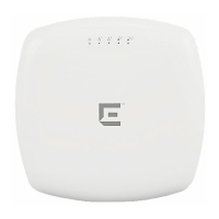
2 (Ethernet link state) LAN 1 On Green Indicates a valid 10Mbps or 100Mbps
Ethernet link.
On Amber Indicates a valid 1Gbps Ethernet link.
Off Indicates the link is down.
3 (Ethernet link state) LAN 2 On Green Indicates a valid 10Mbps or 100Mbps
Ethernet link.
On Amber Indicates a valid 1Gbps Ethernet link.
Off Indicates the link is down.
4 (Radio 2 status) On Green Indicates Radio 2 is enabled.
Off Indicates Radio 2 is not on.
5 (Radio 1 status) On Green Indicates Radio 1 is enabled.
Off Indicates Radio 1 is not on.
Table 1-1 AP3935 LED Indications
LED Status Description

 Loading...
