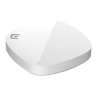
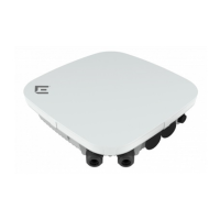
ExtremeWireless™ AP3935 Installation Guide 11
5. Useamagneticscrewdrivertoattachthesmallscrew.DoNOTexceed12in‐lbs oftorque.
6. UseaKensingtonlockforaddedsecurity(seeFigure 1‐5onpage 6).
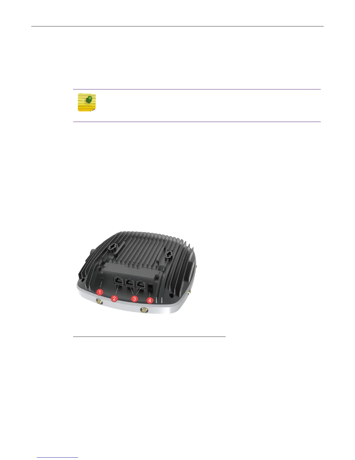
LAN/Console Connections
TheAP3935has2LANportsandaConsoleport.PowerisprovidedthroughtwoEthernetports
(LANports).ThisisthepreferredmethodofpoweringtheAPonceilingandwallinstallations.
TheAPcanbepoweredinoneofthefollowingways:
•PoweroverEthernet(PoE)
Powerisprovidedthrough
theRJ45Ethernetport(LANport)onthetopoftheAP.Thisisthe
preferredmethodofpoweringtheAPonceilingandhighwallinstallations.
•Powerbyexternalpowersupply
WhereaPoE‐capableEthernetconnectionisunavailableorimpractical,anexternal12VDC
powersupplymaybeorderedseparately
topowertheAPfromastandardACwalloutlet.
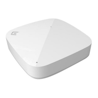
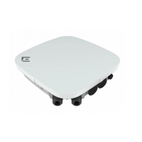
Figure 2-5 3935e Access Point bottom view
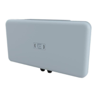
Connecting an External DC Power Supply to the AP3935
Therearenowallmountsforthe12VDCpowersupplies.ToconnectapowersupplytotheAPfor
everydayoperation,mounttheAPandplugthepowersupplyintotheDC‐INport(Callout4in
Figure 2‐5).IfyouhavetakentheAPoffitsmountfor
configurationandmaintenance,theAPstill
needspowerduringthemaintenance.ProvidepowerfromaDCpowersupplyorPoELAN
connector.
NOTE
LAN/Console connectors with shrouds will not fit into the ports. An optional
jumper cable may be used or the shroud removed.
1 Reset Button 3 LAN Ethernet Ports 1 and 2
2 Console Port 4 External Power DC 12V

 Loading...