ExtremeWireless™ AP3935 Installation Guide 9
2. Removetheceilingpanelsaroundthedropceiling T‐barrailandverifythattheEthernetcable
canreachtheAPatthemountingpoint.
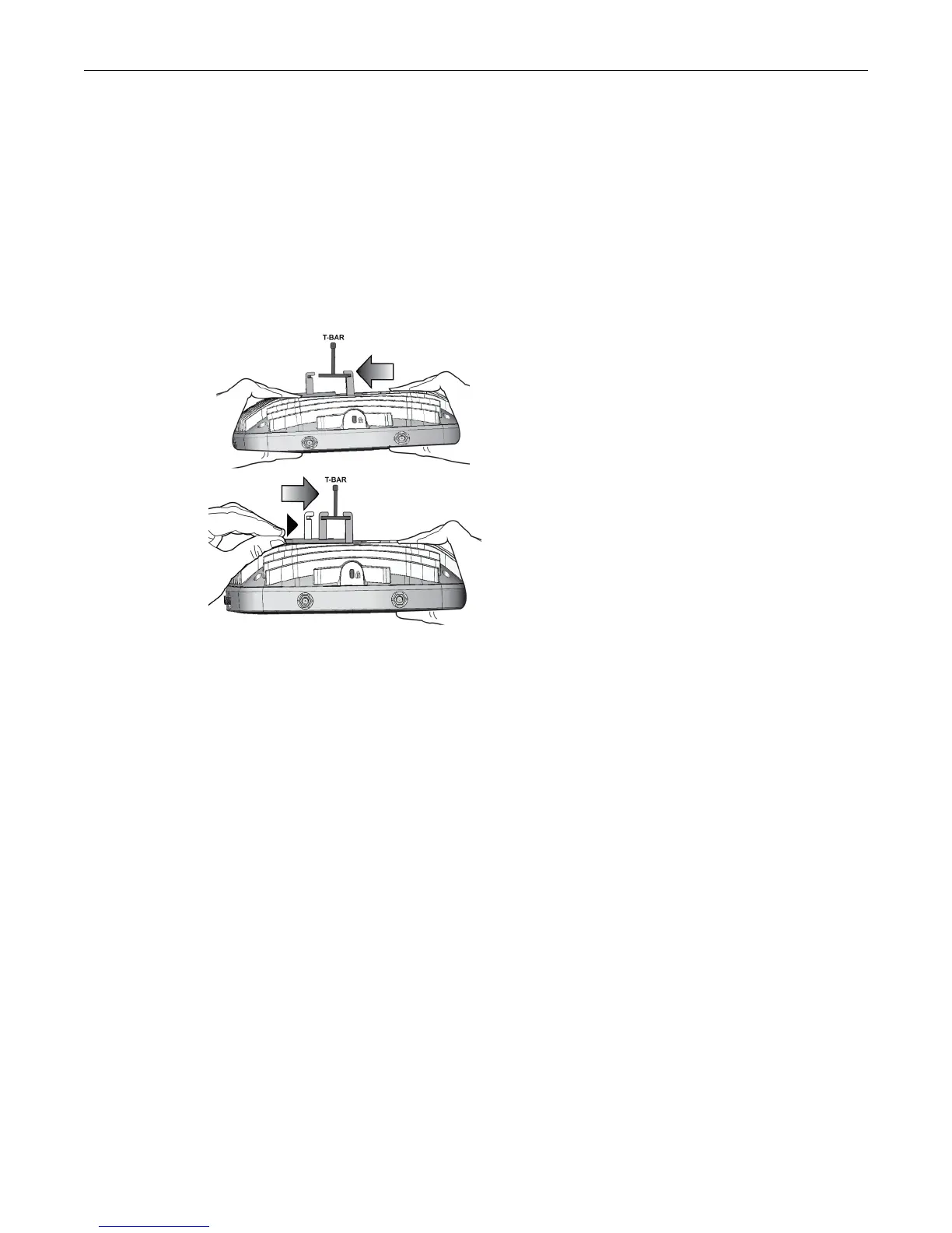
3. SlightlyliftthemovableT‐barlockingtabtoincreasethespacebetweenthestationaryandthe
movableT‐barsidesofthebracket.Thenhook
thestationaryendoftheT‐barbracketontothe
T‐bar,asshowninFigure 2‐2.
4. WhileholdingtheAPwithonehand,reachtheotherhandovertheT‐barandgraspboththe
stationaryandmovablesidesofthebracket.Pushthebracketpartstogethersotheyboth
grasptheT‐barandthelockingtabclicksintoplace.
5. WhilestillholdingtheAP,rockitbackandforthtoensurethatitissecurelymounted.
Figure 2-2 Attaching the AP3935i on a drop ceiling T-bar rail
6. MakeaholethroughtheceilingpanelclosesttothepowerslotontheAP.RuntheEthernet
cablethroughtheholeandintoanRJ45LANportintherecessedconnectorbay.
7. Ifnecessary,cutthe tilesforthecables,attachthecablestotheAP,andreplacethetiles.
8. Replacethedisplacedceilingpanels.
Mounting the AP3935 to a Wall
ScrewsforattachingtheAPtoawallaresuppliedwiththeproduct.Usethefollowingprocedure
tomounttheAP3935toaflatwall:
1. DeterminethespotonthewalltomounttheAP.Pickaspotneartheceiling,butinreachofthe
Ethernetcableandifyou
areusingexternalpower,nearawallpoweroutlet.
2. TomounttheAPdirectlyonthewallwithtwoscrews,usetheprovidedtemplateandmark
thetwodrillholesonthewall.Indrywall,thedrillholesshouldbe6MMto0.250ʺindiameter.
3. Drilltwoholesinthewall
tomatchthecenterofthetwokeyholeslotsinthebackoftheAP
bracket.
4. Screwtheanchorsintotheholesuntiltheyareflushwiththewall.
5. Screwtheprovidedmountingscrewsintotheanchorswiththeheadprotrudingabout5/32”
fromtheanchortothetopofthescrew.

 Loading...